HOOK HEIGHT DISRCI4100 DISPLAY OPTION
MAN-1111 Rev H
©Copyright 2015 LSI-Robway Pty Ltd
Page 165
Operating Instructions (Hook Height)
The following expl ains the Hook Height Encoder. These instructions appl y to both m ain and
au xiliary Hook Height Encoders.
Overview
This RCI-4100 has an integrated Hook Height controller designed to indicate m ain/auxiliary
hook height.
The Hook Height controller works independently from the norm al Rated Capacity Indicator
mode of the RCI-4100 system . It is com prised of the following com ponents integrated into the
system :
•
Winch Encoder. The winch encoder is used to monitor the winch and hook height. The
encoder is usuall y fitted with a suitable drive gear and meshed directly with the crane's
winch. Specifications for the H-38 incremental encoder are at the end of this appendix.
•
Boom Angle Sensor. In addition to its normal function to the Rated Capacity Indicator
mode, the main boom angle sensor is also used in combination with the winch encoder
to monitor hook height.
Note:
Hook Height indication is not a linear measure. The height at either calibration point will be
correct but at other heights is not linear and may not be accurate.
Operation
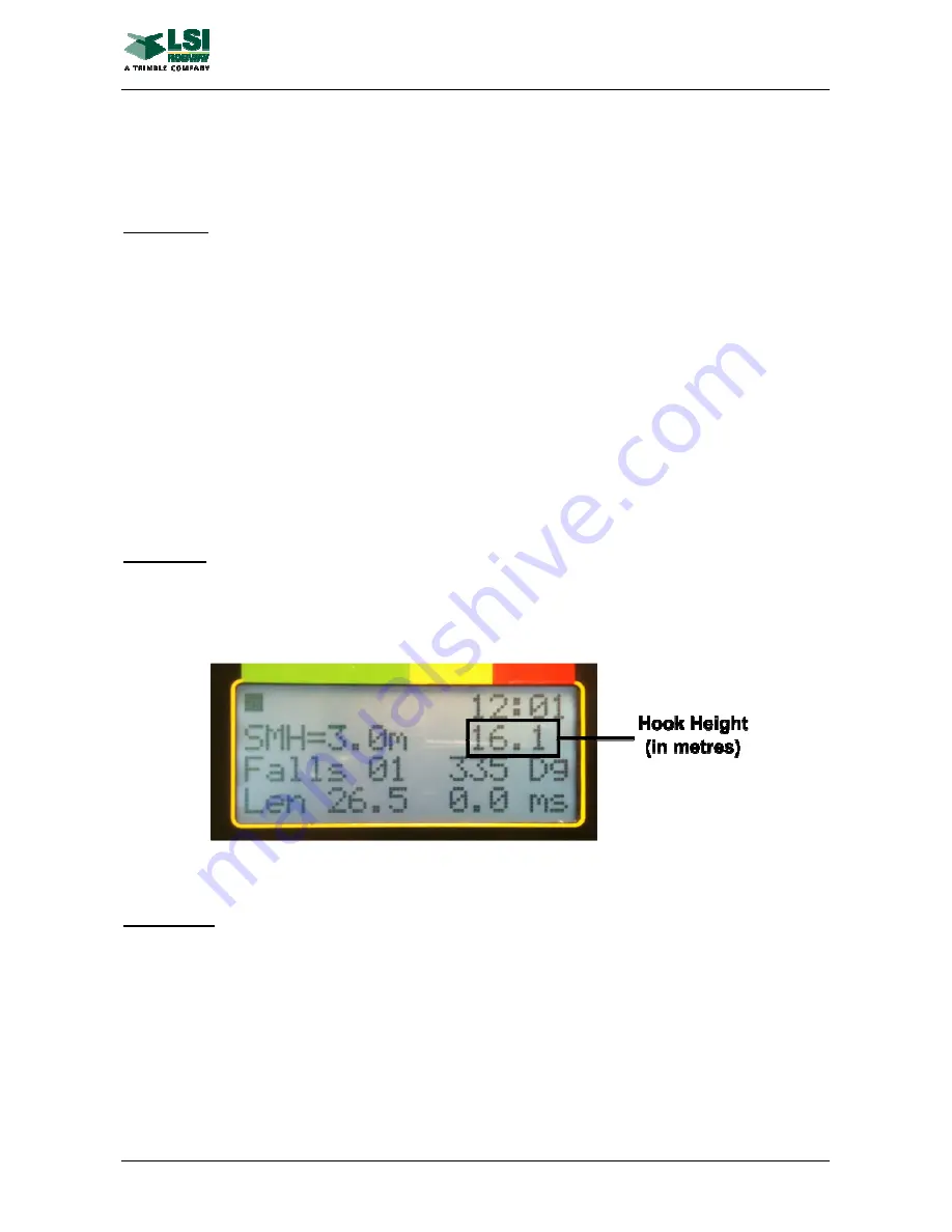
Display
Hook height (for the selected winch) is displayed in the upper display. The picture below illustrates the hook
height display.
Note:
If the RCI-4100 system also has the RSZ option installed, RSZ messages (eg “OBSTACLE”) may
overlay the Hook Height reading.
Calibration
Step 1) Lower the hook to the ground level
Step 2) Enter function code “Calibrate Main Hook Height”, use up/down arrows to select “0.0” and press
“Enter”.
Step 3) “0 DONE” will appear on the display, then “HOOK UP” will appear.
Step 4) Lift the hook to a known height
Step 5) Use up/down arrows to select actual height and press “Enter”.
Step 6) Enter function code “View Main Calibrated Hook Height Input” and confirm that height is accurate
and that height changes when the hook is moving up and down.
Repeat for the Auxiliary using function code “Calibrate Auxiliary Hook Height” to calibrate and “View Auxiliary
Hook Height Input” to view.
Refer RCI System Configuration Documents in Attachments for applicable function codes.
Summary of Contents for RCI-4100
Page 2: ......
Page 6: ......
Page 8: ......
Page 28: ......
Page 36: ......
Page 58: ......
Page 70: ......
Page 82: ......
Page 88: ......
Page 92: ......
Page 94: ......
Page 100: ......
Page 102: ......
Page 104: ......
Page 106: ......
Page 108: ......
Page 110: ......
Page 112: ......
Page 114: ......
Page 126: ......
Page 128: ......
Page 130: ......
Page 132: ......
Page 140: ......
Page 142: ...WIND SPEED MONITORING OPTION MAN 1111 Rev H Copyright 2015 LSI Robway Pty Ltd Page 142 ...
Page 144: ......
Page 147: ...WIND DIRECTION MONITORING MAN 1111 Rev H Copyright 2015 LSI Robway Pty Ltd Page 147 ...
Page 148: ......
Page 150: ......
Page 156: ......
Page 158: ......
Page 162: ...TILT SENSING OPTION MAN 1111 Rev H Copyright 2015 LSI Robway Pty Ltd Page 162 ...
Page 164: ......
Page 170: ......
Page 171: ...SYSTEM DRAWINGS MAN 1111 Rev H Copyright 2015 LSI Robway Pty Ltd Page 171 ...
Page 172: ...SYSTEM DRAWINGS MAN 1111 Rev H Copyright 2015 LSI Robway Pty Ltd Page 172 ...
Page 173: ...SYSTEM DRAWINGS MAN 1111 Rev H Copyright 2015 LSI Robway Pty Ltd Page 173 ...
Page 174: ...SYSTEM DRAWINGS MAN 1111 Rev H Copyright 2015 LSI Robway Pty Ltd Page 174 ...
Page 175: ...SYSTEM DRAWINGS MAN 1111 Rev H Copyright 2015 LSI Robway Pty Ltd Page 175 ...
Page 176: ...SYSTEM DRAWINGS MAN 1111 Rev H Copyright 2015 LSI Robway Pty Ltd Page 176 ...
Page 177: ...SYSTEM DRAWINGS MAN 1111 Rev H Copyright 2015 LSI Robway Pty Ltd Page 177 ...
Page 178: ...SYSTEM DRAWINGS MAN 1111 Rev H Copyright 2015 LSI Robway Pty Ltd Page 178 ...
Page 179: ...SYSTEM DRAWINGS MAN 1111 Rev H Copyright 2015 LSI Robway Pty Ltd Page 179 ...
Page 180: ......
Page 182: ......


