IDENTIFYING/INSTALLING PERMANENT FLOOR SUPPORTS
GENERAL INSTALLATION INFORMATION
SLAVE DRIVE / MATING TO OTHER CONVEYORS
NOTE:
There are two primary methods of
installation for a curve--driven by its own
gear motor or SLAVE driven from another
conveyor.
Once conveyor is uncrated, installation of
curve or spur may begin (note that in follow-
ing text we will use “curve” for reference to
both curves and curve spurs). Locate unit in
the actual installation area.
There are two primary methods of instal-
lation for a curve--driven by its own gear
motor or SLAVE driven from another con-
veyor. Most often, curves are SLAVE driven
by belt driven live rollers or slider bed belt
conveyors, which eliminates gear motor
drive assembly for curve.
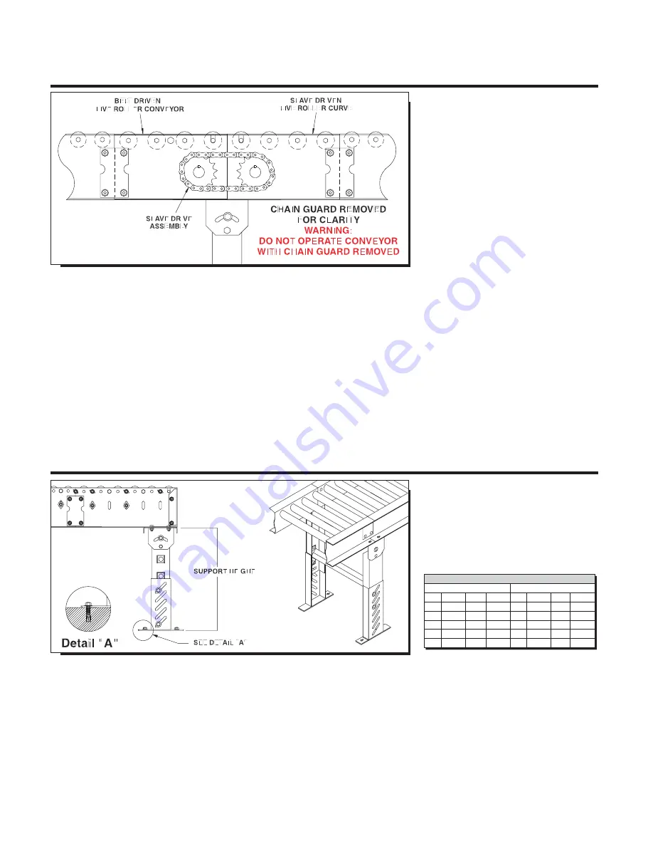
Locate actual bed section of conveyor
which is to slave drive curve to begin instal-
lation. Note that this conveyor is usually
set up before curve is installed. Bed sec-
tion labels are located on bed of driving
conveyor showing where slave driven curve
will be installed (see illustration above). For
curves not slave driven, location of instal-
lation in most usually noted by conveyor
“mark numbers”.
Use mechanical hoist (fork truck or other
available means) to raise bed sections to
approximate installed elevation. Locate sup-
ports, attach to curve and mate curve with
butt couplings.
It is most common to use single tier perma-
nent floor supports at each end of a curve,
for models 138LRC and 196LRC. In the
center of the curve, a single leg support is
required underneath the outside frame rail.
If the frame rail consists of two or more
frame rails
and
is joined together in the cen-
ter of the curve, a full support is required.
For model 138LRCS and 196LRCS curve
spurs, two supports are generally required,
one support at the junction between the
spur and the curve and one support at the
tangent end of the curve.
Adjust elevation to top of conveyor by
loosening bolts in support uprights, raising
or lowering conveyor and fully tightening
bolts at desired elevation. Tighten all bolts
in supports
before
unit operation.
Complete support installation by lagging
support attachment plates to floor with two
lag bolts in a diagonal pattern in support
foot plate mounting holes. Conveyor
must be level across width of unit before
completing final support height adj.
*Supports are normally shipped at minimum
support height. See chart above.
CAUTION: Always
anchor permanent sup-
ports to floor (or mounting surface). Use
3/8” x 2-1/2” (or longer) wedge anchors
for permanent installation in
concrete flooring.
*MINIMUM SUPPORT HEIGHT
MEDIUM DUTY
HEAVY DUTY
SM-1
7-1/4”
SM-7
34-1/4” SH-1
6-1/4”
SH-7
25-3/4”
SM-2 10-1/4”
SM-8
46-1/4” SH-2
7-3/4”
SH-8
31-3/4”
SM-3 13-1/4”
SM-9
58-1/4” SH-3 10-3/4”
SH-9
43-3/4”
SM-4 16-1/4” SM-10 70-1/4” SH-4 13-3/4” SH-10 55-3/4”
SM-5 20-1/4” SM-11 80-1/4” SH-5 16-3/4” SH-11 67-3/4”
SM-6 24-1/4” SM-12 92-1/4” SH-6 19-3/4” SH-12 29-3/4”
5
Summary of Contents for 138LRC
Page 1: ......
Page 9: ...V BELT PATHS V BELT PATH FOR SPURS AND CURVES 9...
Page 17: ...MODEL 138LRC ILLUSTRATIONS FOR UNIT WITH END DRIVE SIDE MOUNT END DRIVE 17...
Page 19: ...MODEL 196LRC ILLUSTRATIONS FOR UNIT WITH END DRIVE SIDE MOUNT END DRIVE 19...
Page 21: ...MODEL 138LRCS ILLUSTRATIONS FOR UNIT WITH END DRIVE SIDE MOUNT END DRIVE 21...
Page 23: ...MODEL 196LRCS ILLUSTRATIONS FOR UNIT WITH END DRIVE SIDE MOUNT END DRIVE 23...


