background image


Importing from an SD Card • 112

 5 . Click the 

SD Import

 button.

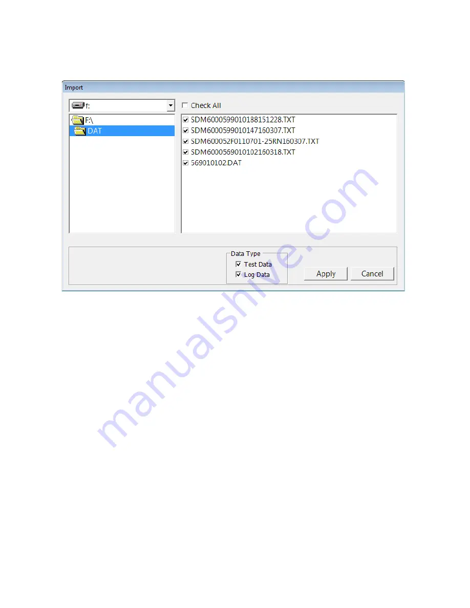
 6 . Navigate to the SD card location on your computer.

 7 . Select the types of data you want to import. 

Test Data

 is data from bump tests, 

calibrations, and alarm checks done with the SDM-6000 (in either Standalone 
or PC Controlled Mode) and is saved as a .txt file. It will not include data from 
tests done away from the SDM-6000. 

Logs Data

 is saved instrument data that 

was downloaded to the SD card during a data download (in Standalone Mode 
only) and is saved as a .dat file. It will include Interval Trend data, Alarm Trend 
data, etc. If you select 

Test Data

, only .txt files will be displayed for selection. If 

you select 

Logs Data

, only .dat files will be displayed.

 8 . Select the files that you want to import or use the Check All box to select all of 

the files.

 9 . Click 

Apply

. A window will appear for a few seconds indicating that the file or 

files are being imported.

 10 . The files are now added to the database.

 Figure 58: SD Card Import Window

Summary of Contents for SDM-6000

Page 1: ...www rkiinstruments com SDM 6000 Docking Station Standalone Configuration Operator s Manual Part Number 71 0385 Revision A Released 2 28 17 ...

Page 2: ...sts local repair costs transportation costs or contingent expenses incurred without our prior approval THIS WARRANTY IS EXPRESSLY IN LIEU OF ANY AND ALL OTHER WARRANTIES AND REPRESENTATIONS EXPRESSED OR IMPLIED AND ALL OTHER OBLIGATIONS OR LIABILITIES ON THE PART OF RKI INSTRUMENTS INC INCLUDING BUT NOT LIMITED TO THE WARRANTY OF MERCHANTABILITY OR FITNESS FOR A PARTICULAR PURPOSE IN NO EVENT SHAL...

Page 3: ... 6 Overview 6 SDM 6000 Components 6 Touch Screen 7 Status LED 12 Instrument Cradle 12 Gas In Gas Out Cover 12 Left Panel Components 13 Mating Slave Connections 15 Exhaust Fitting 16 Air Filter and Exhaust Tubing 17 Connection Brackets 17 Accessories Included in Various Bundles 18 AC Adapter 18 USB Cable 19 Ethernet Cable 19 SD Card and SD to USB Reader 19 Demand Flow Regulator 19 Calibration Tubin...

Page 4: ...Attached 33 Connecting Calibration Gas SV 3 Attached 35 Setting Basic Operational Parameters in the Config Menu 38 Bump Test Parameters 38 Calibration Parameters 44 Inlet Parameters 47 Date Time and Date Time Format 51 Language 54 Password 56 Setting Detailed Operational Parameters Using the SDM PC2 Docking Station PC Controller Program 59 Launching the PC Controller Program 60 Accessing the SDM C...

Page 5: ...s Too Drained for Standalone Operation 107 Bump Test Calibration and Alarm Check Records 108 Available Memory in the SD Card 108 Test Record Files 108 Transferring Record Files to a Computer 109 Chapter 5 Importing Data Into the SDM PC2 Docking Station PC Controller Program 110 Overview 110 Importing from an SD Card 110 Importing Using the LAN Network 113 Viewing Imported Data 116 Exiting the Prog...

Page 6: ... computer s hard drive if the files have been transferred to the hard drive from the SDHC card If you are using the PC Controller Program while operating in the PC controlled configuration you may retrieve instrument data bump test calibrate and alarm check instruments Instrument information and data for each instrument can be viewed directly using the PC Controller Program and can be printed from...

Page 7: ...tection provided by the equipment may be impaired System Requirements To use the SDM PC2 Docking Station PC Controller Program your personal computer must meet the following requirements Operating Systems Windows 7 Windows 8 Windows 10 Processor IBM compatible PC running Pentium 2 processor or equivalent minimum Memory 32 MB RAM minimum Hard Disk Space 32 MB minimum Available USB Port SD Card Slot...

Page 8: ... to 40 C below 95 Relative Humidity Non Condensing Applicable Instrument GX 6000 Memory Capacity Dependent on capacity of installed SDHC card Record Size 1 1 KB bump test calibration alarm check Maximum Number of Records Saved Dependent on capacity of installed SDHC card Number of Calibration Gas Cylinders SV 3 not connected Up to three calibration gas cylinders per bump test or calibration at a t...

Page 9: ...ystems where none of the 5 stations are connected together each system will need 1 each of the starred items which means you will have a total of 5 each of the starred items For this system you would need to order 5 81 SDM6000 01 bundles 5 81 SDM6000 03 bundles or 5 81 SDM6000 04 bundles depending on additional accessories desired If you have 1 multi station system with 5 SDM 6000s connected toget...

Page 10: ...X X X X Single Station AC Adapter a X X X Multi Station AC Adapter b X SDHC Card with SD to USB Reader X X X X Demand Flow Regulator X X Calibration Tubing 3 ft Length X X Calibration Cylinder Holder X Calibration Cylinder X Each system needs only one each of these a Used only for single station systems b Used only for multi station systems Type of calibration cylinder depends on bundle ordered Bu...

Page 11: ... optional accessories that are not included in any bundles SDM 6000 Components The SDM 6000 consists of the touch screen status LED instrument cradle gas in gas out cover left panel mating slave connections exhaust fitting air filter exhaust tubing and connection brackets Instrument Cradle Gas In Gas Out Cover Status LED S TA TU S Touch Screen Instruction Label Figure 1 SDM 6000 Component Location...

Page 12: ... In a multi SDM 6000 system the master leftmost SDM 6000 s touch screen includes the Function and Unit Tabs and any slave SDM 6000s touch screens only display the Unit Tab information The Function and Unit tabs are described below in Function Tab and Unit Tab Figure 2 Single SDM 6000 System Touchscreen Figure 3 Multi SDM 6000 System Touchscreens Master Touchscreen Slave Touchscreen ...

Page 13: ...n SD card is inserted in the SD card slot and the status of an inserted SD card Table 3 SD Card Logo Colors The cylinder logo in the bottom left corner of the Function Tab indicates the expiration status of the calibration cylinders In order to set up the expiration status the docking station must be connected to the PC Controller Program and the cylinder information entered into the Cylinders Tab...

Page 14: ...te with no icon an SDM 6000 is installed in that position and the corresponding SDM 6000 has no instrument connected to it If an indicator is a color other than light grey and an icon appears in it then the corresponding SDM 6000 has an instrument installed and connected to it Table 5 Docking Station Indicator Background Colors Cylinder Color Meaning Grey Expiration date more than 10 days away OR ...

Page 15: ... station in a multi station system The text field above the gas combination which shows instrument or station status and the Detector On Detector Off button in the lower left which turns the GX 6000 on and off are common to each variation of the Unit Tab Icon Meaning None GX 6000 is not connected GX 6000 is connected and Unit Tab s Active box is selected GX 6000 is connected and Unit Tab s Active ...

Page 16: ...ument is connected In a multi station system the Auto Bump selection box will not appear The Active selection box appears in the lower right corner of the screen in a multi station system and includes or excludes an instrument from any testing It appears on both the master and slave stations The Download button appears in the lower right corner of the screen in a single station system and in the l...

Page 17: ...t when it is inserted in the cradle and is used to communicate with the GX 6000 Charging contacts in the bottom of the cradle line up with the GX 6000 s charging contacts Gas In Gas Out Cover The red gas in gas out cover mates to the GX 6000 s inlet and exhaust fittings and routes calibration gas to and from the GX 6000 The cover is spring loaded To connect the cover to the GX 6000 push it down un...

Page 18: ...D card is not installed no data will be saved during testing USB PC Connector A type B USB connection allows for the SDM 6000 to be connected to a PC using a Type A to Type B USB cable Connection to a PC is necessary for setting up the LAN function and for using the SDM 6000 in its PC controlled configuration This manual explains how to set up the LAN function but does not cover PC controlled conf...

Page 19: ...e white on off switch turns the station on or off Push the top of the switch toward the station to turn it on Push the bottom of the switch toward the station to turn it off Power Jack The round power jack is located below the on off switch The plug on the end of the AC adapter cable mates to it Electrical Connector The black electrical connector allows for an electrical connection to another SDM ...

Page 20: ...DM 6000 is being used alone or if it is the right most station in a bank of connected stations The panel needs to be removed in order to connect another SDM 6000 to it Beneath the panel is a mating electrical connection and plugged mating sample fitting connections Mating Sample Fittings Plugged Panel Removed Panel In Place Mating Electrical Connection Panel Figure 8 Right Panel Component Location...

Page 21: ...routing of the exhausted calibration gas to a convenient location This fitting accepts 5 16 inch ID tubing Even though the exhaust gas can be routed to an area to be safely dispersed the docking station should still be installed in a well ventilated area Exhaust Fitting Figure 9 Back Panel Component Location ...

Page 22: ...t fitting on the back panel to allow routing of the exhaust to a location such as an open window where the exhaust can disperse WARNING Do not use an exhaust tube that is longer than 15 feet The increased flow restriction caused by a longer tube may affect gas response and cause inaccurate calibration and bump test results Connection Brackets Each SDM 6000 is provided with 3 connection brackets th...

Page 23: ...00 bundles include these items AC Adapter Single Station AC Adapter The single station AC adapter is a wall plug style adapter with a 5 foot cable The end of the cable has a plug that connects to the SDM 6000 s power jack The AC adapter is rated 100 240 VAC input 24 VDC 0 63 A output Multi Station AC Adapter The multi station AC adapter is a larger adapter with a separate power cord and a plug tha...

Page 24: ...he building s network ports If you have a multi station system the ethernet cable only needs to be plugged into the master leftmost station SD Card and SD to USB Reader The SDHC card needs to be installed in the SD card slot on the left side of the SDM 6000 in order for data to be saved If you have a multi station system the SD card only needs to be inserted into the master leftmost station s SD c...

Page 25: ...s connected together the SV 3 will be installed on the left most SDM 6000 The SV 3 comes with 2 connection brackets that are used to mechanically connect the SV 3 to the left most SDM 6000 Printer The printer supported by the SDM 6000 is the Seiko Instruments Inc DPU S245 USB printer It allows for quick printing of bump test or calibration results The printer comes with an AC adapter and power cor...

Page 26: ...Program is not required for Standalone operation but is needed to import and view data and to access some setup parameters that cannot be accessed in the SDM 6000 s Config Menu 1 Launch Windows 2 Exit from all applications and open windows 3 Go to www rkiinstruments com sdm6000 4 Click on the Download tab 5 Click the SDM PC2 PC Controller Software link 6 A zip file will begin to download Select wh...

Page 27: ...lick Install and the installation process will begin If you want to change installation settings click Back and change them to the desired settings 15 During software installation the installation program may find newer versions of Windows files on your computer than those in the downloaded zip file If this happens the installation software will ask you if you want to keep these newer files Click ...

Page 28: ...cognized by the computer The status bar will indicate that the drivers are being configured and will alert you when the SDM 6000 is ready to use Connecting Multiple SDM 6000s Together Up to 10 SDM 6000s can be connected together The leftmost SDM 6000 is the master station and the remaining stations are slave stations If you remove the leftmost SDM 6000 from the setup the station that is now the le...

Page 29: ...igure 17 Panel and Plug Removal 3 Starting with the two left most stations line up the mating electrical connections and sample fitting connections and push the two stations together until the housings are touching 4 Add stations to the right side of the bank using the same procedure The last station installed should be the one that still has a panel on the right side Panel In Place Panel Removed ...

Page 30: ...ether 5 Use the provided metal connection brackets and screws to secure the two connection points on each side of the SDM 6000 s back panel and on the bottom of the SDM 6000 to each other Figure 18 Connecting SDM 6000s Together Back Panel ...

Page 31: ...Connecting Multiple SDM 6000s Together 26 Figure 19 Connecting SDM 6000s Together Bottom Panel ...

Page 32: ...ng sample fitting connections on the SV 3 with the electrical connector and sample fittings on the left side of the left most SDM 6000 3 Push the SV 3 toward the SDM 6000 until the housings are touching 4 Use the provided metal connection brackets and screws to secure the back and bottom of the SV 3 to the SDM 6000 Figure 20 Connecting the SV 3 Bottom Panel Back Panel ...

Page 33: ... the hardware assembly 1 Place the SDM 6000 s on a convenient table top near an AC wall socket in a well ventilated area A location near a window that can be opened is best so that the exhaust can be routed to the window 2 Connect the AC adapter s wall plug into a wall AC socket 3 Insert the round plug on the end of the AC adapter s output cable into the power jack on the back of the SDM 6000 NOTE...

Page 34: ...e tube to an area where the exhaust can be safely dispersed such as an open window CAUTION The maximum recommended length for the exhaust tube is 15 feet Do not use more than 15 feet of tubing or tubing with an ID of less than 5 16 inch for the exhaust tube or the bump test and calibration accuracy may be adversely affected The tube that is shipped with the SDM 6000 has an ID of 5 16 inch and is 1...

Page 35: ...onal 30 Figure 21 Wall Mounting 1 7 SDM 6000s 1 SDM 6000 2 4 SDM 6000s 5 7 SDM 6000s of SDM 6000s w SV 3 or w o SV 3 3 wall mounting brackets 6 wall mounting brackets 9 wall mounting brackets Total of wall mounting brackets necessary ...

Page 36: ... wall mount since access to the exhaust fitting will be very limited once the SDM 6000 is mounted to the wall 1 If you are mounting multiple SDM 6000s be sure your SDM 6000s are properly connected and secured to each other If you are using an SV 3 be of SDM 6000s w SV 3 or w o SV 3 8 10 SDM 6000s Total of wall mounting brackets necessary 12 wall mounting brackets ...

Page 37: ...ion has a smaller hole than the long section Screw the short section into the SDM 6000 making sure that the long section goes away from the station and is flush with the back of the SDM 6000 Figure 23 Wall Mounting Bracket Installation 3 Position the SDM 6000 s on the wall where you intend to mount them 4 Screw the wall mounting brackets into the wall Make sure the mounting Long Section w Bigger H...

Page 38: ...ngs are normally used for smart sensors i e PID ESS 03 etc If you have a smart sensor installed i e PID ESS 03 etc a special cylinder for the target gas of that sensor needs to be used for calibration See the tables below for examples of needed cylinders for various GX 6000 combinations Keep in mind that if you are going to use a 5 gas cylinder to calibrate one of the smart sensors make sure that ...

Page 39: ...as Ports for Multi Station Use Standard 4 gas high range PID NH3 GAS 1 5 gas mix with LEL Oxy CO H2S IBL GAS 2 NH3 Standard 4 gas SO2 GAS 1 5 gas mix with LEL Oxy CO H2S SO2 Instrument Types Recommended Calibration Gas Cylinder and Gas Inlet Selection Instrument 1 3 gas low range PID Instrument 2 3 gas high range PID GAS 1 3 gas mix with LEL Oxy CO GAS 2 10 ppm IBL GAS 3 100 ppm IBL Instrument 1 3...

Page 40: ... flow regulator to the appropriate inlet fitting using 3 16 inch ID sample tubing Connecting Calibration Gas SV 3 Attached The GAS 1 GAS 2 GAS 3 GAS 4 GAS 5 and GAS 6 fittings on the left side of the SV 3 are designed to be used with a calibration gas cylinder that is fitted with a demand flow regulator The AIR fitting may be used with a demand flow regulator and a cylinder of zero emissions air b...

Page 41: ...n the GAS 1 fitting may be used for gas to test a smart sensor The SV 3 is useful for single station use or multi station use If you have multiple GX 6000 configurations instead of having to reassign GAS 2 or GAS 3 every time you test a different configuration like you would have to do if an SV 3 was not installed you can assign the different gases to GAS 4 GAS 5 or GAS 6 The gas inlets can be ass...

Page 42: ...ulator s on the calibration gas cylinder s Instrument 1 Standard 4 gas high range PID Instrument 2 Standard 4 gas high range PID NH3 Instrument 3 Standard 4 gas SO2 NO2 GAS 1 5 gas mix with LEL Oxy CO H2S IBL GAS 2 NH3 GAS 3 SO2 GAS 4 NO2 Instrument 1 Standard 4 gas NH3 Instrument 2 Standard 4 gas SO2 Instrument 3 High range PID NO2 GAS 1 4 gas mix with LEL Oxy H2S CO GAS 2 NH3 GAS 3 SO2 GAS 4 100...

Page 43: ...ou have multiple SDM 6000s connected together the slave SDM 6000s will use the same parameter values of the master SDM 6000 The parameters cannot be changed for each individual SDM 6000 if they are all connected together If the master SDM 6000 is removed from the installation it will retain its settings but the new master SDM 6000 that is now the left most SDM 6000 will not remember the old master...

Page 44: ...pass the bump test It is defined as a percentage of the calibration gas concentration The amount that the GX 6000 gas reading differs from the calibration gas concentration must be equal to or less than this percentage of the calibration gas concentration For example if the tolerance is set to 50 and the LEL calibration gas concentration is 50 LEL then the bump test gas reading for the LEL channel...

Page 45: ...0 which means that the acceptable reading range is 25 LEL 75 LEL Fast selected The table below shows possible readings at 10 seconds and the effect on the gas application Automatic Calibration Auto Cal Automatic calibration only applies to bump testing It can be set to On or Off If it is set to On then the docking station will automatically perform a calibration if a bump test fails Alarm Check If...

Page 46: ...ly print bump test results but the results can still be printed by pressing the Print button at the end of a bump test Viewing or Changing the Bump Parameters Do the following to set the bump test parameters 1 Turn on the SDM 6000 system The Function Tab will be displayed on a single station system s screen or on the master station s screen in a multi station system 2 Press the Config button If Pa...

Page 47: ...Setting Basic Operational Parameters in the Config Menu 42 3 The Configuration Menu will be displayed 4 Press the BUMP button The 8 bump test parameters and their current settings will be displayed ...

Page 48: ...hanges and return to the Bump Parameters Screen d Press cancel to return to the Bump Parameters Screen without saving the changes e Repeat step a step d to set any other parameters 6 Select or deselect the Fast Auto Cal Alarm Check and Auto Print parameters to turn them on or off 7 When you are done setting the parameters press the Return arrow button on the right side of the screen The Configurat...

Page 49: ...w air through the AIR fitting to purge calibration gas from the system Alarm Check If Alarm Check is selected a vibrator LED and buzzer test is done on the GX 6000 at the end of the bump test The vibrator will vibrate the LEDs will turn on for a few seconds the buzzer will sound and the SDM 6000 will determine if these actions were completed successfully Auto Print The printer must be connected fo...

Page 50: ...ing the Calibration Parameters Do the following to set the calibration parameters 1 Turn on the SDM 6000 system The Function Tab will be displayed on a single station system s screen or on the master station s screen in a multi station system 2 Press the Config button If Password is set to on factory setting is off you will be prompted for a password Enter the password and press OK to continue ...

Page 51: ...he CAL button The 5 calibration parameters and their current settings will be displayed 5 Adjust the AIR Flush GAS and AIR Purge parameters as described below The procedure is the same for each parameter s adjustment AIR Flush is shown as an example a Press the current value for the parameter you want to change ...

Page 52: ... s main menu press the return arrow on the right side of the screen Inlet Parameters The gas inlet parameters define what gases are assigned to each port and lets you select the ports as active or inactive All of the standard 4 sensors catalytic LEL O2 H2S and CO are generally assigned to GAS 1 If the SV 3 is not being used smart sensors PID ESS 03 etc are generally assigned to GAS 2 and GAS 3 If ...

Page 53: ... the Config Menu 48 3 Press the Config button If Password is set to on factory setting is off you will be prompted for a password Enter the password and press OK to continue 4 The Configuration Menu will be displayed 5 Press the Inlet button ...

Page 54: ...or a test For example if you have a 4 gas low range PID GX 6000 but you only want to test the PID sensor you could deselect the Active button for the 4 gas inlet NOTE Since the SDM 6000 only has 3 gas ports GAS 4 GAS 5 and GAS 6 cannot be selected as active if the SV 3 is not connected Gas list in the middle of the screen shows what gas es are assigned to the selected inlet 6 To change the gas es ...

Page 55: ... the current selection f Press OK to save the changes and return to the Inlet Parameter screen g Press Cancel to return to the Inlet Parameter screen without saving any changes 7 Use the arrows above and below the gas inlet selection to change the gas inlet The Active parameter s setting and the gas list will change 8 Repeat steps 5a 5g for any additional channels you wish to assign an inlet to 9 ...

Page 56: ...s date time or date time format 1 Turn on the SDM 6000 system The Function Tab will be displayed on a single station system s screen or on the master station s screen in a multi station system 2 Press the Config button If Password is set to on factory setting is off you will be prompted for a password Enter the password and press OK to continue ...

Page 57: ...Setting Basic Operational Parameters in the Config Menu 52 3 The Configuration Menu will be displayed 4 Press the Date button 5 To change the date a Press the Date field ...

Page 58: ...urn to the Configuration Menu without saving any changes 6 To change the time a Press the Time field b To change any of the settings use the arrows below the setting or press the current setting and type in the desired value on the number pad that appears If the station is not using 24 hour time the arrows below the hour must be used to scroll through the AM and PM times c Press OK to save the cha...

Page 59: ...year b Select or deselect the 24H box to turn the 24 hour clock function on or off c Press the return button to return to the Configuration Menu Language Follow the instructions below to change the station s language 1 Turn on the SDM 6000 system The Function Tab will be displayed on a single station system s screen or on the master station s screen in a multi station system ...

Page 60: ...s the Config button If Password is set to on factory setting is off you will be prompted for a password Enter the password and press OK to continue 3 The Configuration Menu will be displayed 4 Press the Language button The available language options will be displayed ...

Page 61: ...ght away 6 Press the return button to return to the Configuration Menu Password If Password is set to on a password will be required to enter the Configuration Menu If Password is set to off factory setting no password is required to enter the Configuration Menu Do the following to turn Password on or off 1 Turn on the SDM 6000 The Function Tab s main menu will be displayed 2 Press the Config butt...

Page 62: ...rational Parameters in the Config Menu 3 The Configuration Menu will be displayed 4 Press the Password button The Password Menu will appear 5 To turn the password function on or off select or deselect the Use selection box ...

Page 63: ...ou will be prompted to enter the current password The factory set password is 0000 Enter the current password and press OK to proceed or Cancel to return to the Password Menu b You will be prompted to enter the new password Enter the new password and press OK to proceed or Cancel to return to the Password Menu ...

Page 64: ...eration but are only accessible using the PC Controller program are Data Logger set up the SDM 6000 to automatically download the GX 6000 s logger data to the SD card every time it s turned on or at an interval enable or disable manual downloading of the GX 6000 s logger data to the SD card Power Saving select how much time goes by before the GX 6000 is automatically turned off after a successful ...

Page 65: ... and the main program window appears Figure 24 Main Program Window 2 If you are starting the software for the first time a message window appears informing you that a database has been created Click OK in that window 3 Connect the AC adapter to the SDM 6000 and to an AC wall socket If you have a multi station system only the leftmost SDM 6000 should be connected to power 4 Connect a Type A to Type...

Page 66: ...n 2 Click the SDM button at the top of the screen 3 If the Password parameter in the Bump Cal 2 Tab of the SDM Configuration Window or in the SDM 6000 s Config Menu is set to ON the program will prompt you for a password to enter the SDM Configuration Window Enter the password and click OK 4 The SDM Configuration Window will open and the Bump Cal 1 Tab will be displayed Figure 25 SDM Configuration...

Page 67: ...ick the Bump Cal 2 Tab Figure 26 Bump Cal 2 Tab 4 Use the drop down menu to select the desired setting for the Data Logger Auto Download parameter OFF No data download to the SD card will be performed when a GX 6000 is connected to the SDM 6000 Every Time A data download to the SD card will automatically occur every time a GX 6000 is connected to the SDM 6000 Interval A data download to the SD car...

Page 68: ...Manual Download to the desired setting When set to ON default value the Download button on the SDM 6000 touchscreen becomes active and a manual download in Standalone Mode of the GX 6000 s logger data to the SD card can be performed When set to OFF the Download button is not active and a manual download of the GX 6000 s logger data to the SD card cannot be performed in Standalone Mode 7 To save th...

Page 69: ...s The factory setting is 15 seconds 5 Select the desired setting for the Auto Power Off parameter This is the length of time that will pass after the last operation is finished before the docking station will automatically shut off the GX 6000 If a successful bump test calibration or alarm check is performed the docking station will automatically shut off the GX 6000 in the time defined in Power O...

Page 70: ... SDM Configuration Window as described in Accessing the SDM Configuration Window on page 61 3 Click the Bump Cal 2 Tab Figure 28 Bump Cal 2 Tab 4 Select the desired setting for the Calibration Expiration Notice parameter This is the length of time in days before a GX 6000 is due for calibration that the SDM 6000 will give an indication that the GX 6000 s calibration due date is approaching So if c...

Page 71: ...ner of the SDM 6000 s Function Tab will change from green to orange 6 To save the changes click SDM Update and click Yes in the window that appears To return to the main window without saving any changes click Cancel and click OK in the window that appears Updating the Automatic Execution Settings The Automatic Tab allows you to set up a bump test calibration or alarm check to automatically occur ...

Page 72: ...n or type in the desired value 6 Select what day s you would like the test to be done in the Weekly Execution area 7 To save the changes click SDM Update and click Yes in the window that appears To return to the main window without saving any changes click Cancel and click OK in the window that appears Updating the Cylinders Settings This section describes how to use the Cylinders Window to update...

Page 73: ...er Program and can be set using the SDM 6000 s Config Menu In order to provide more comprehensive instructions this section will include instructions for setting parameters that can also be set using the SDM 6000 s Config Menu Figure 30 Cylinders Window The Cylinders Window shows the cylinder name cylinder part number expiration date and active status for each cylinder Selecting a Cylinder from th...

Page 74: ...w 4 Double click the line or single click the line and click Edit that corresponds with the gas inlet you d like to set up For example double click line 3 or single click line 3 and click Edit to set up a cylinder for the GAS 3 inlet on the SDM 6000 or SV 3 The Cylinder Detail window will display Figure 32 Cylinder Detail Window ...

Page 75: ...C2 Docking Station PC 5 The pre defined cylinders list is located in a drop down menu at the bottom of the window Click the drop down arrow to view the pre defined cylinders list Scroll down to view additional cylinders Figure 33 Pre Defined Cylinders List ...

Page 76: ...g the SDM PC2 Docking 6 Click the cylinder you d like to use In this example Cl2 has been selected The Name Part No Symbol Unit and Concentration fields will automatically be filled in Figure 34 Cylinder Detail Window Filled In with Pre Defined Info ...

Page 77: ... cylinder will turn red if the expiration date has passed 9 Select or deselect the Active box for each cylinder If the cylinder is active the PC Controller Program will alert you at start up if the cylinder has passed its expiration date and will include the associated inlet in testing If it is not active the program will not alert you if the cylinder has passed its expiration date and will not in...

Page 78: ...n the window that comes up Defining New Cylinders If your GX 6000 configuration requires the use of a cylinder that is not in the predefined list you can add that cylinder by either typing in the information for the cylinder or by editing the information for an existing cylinder 1 Launch the PC Controller Program and connect your SDM 6000 s as described in Launching the PC Controller Program and C...

Page 79: ...3 inlet on the SDM 6000 or SV 3 The Cylinder Detail window will display Figure 37 Cylinder Detail Window 5 Click in the Name field and type in a name for the cylinder Use something descriptive that will help you distinguish it from other cylinders You can also select a pre defined cylinder and then edit the name that is automatically generated 6 If you want to enter a part number for the cylinder ...

Page 80: ...ing the SDM PC2 Docking 7 Enter a gas symbol for each cylinder component you want to identify Click in the Symbol field of the desired line and type in characters or click the drop down arrow and select a symbol from the list Figure 38 Symbol List ...

Page 81: ...e Cylinders Window that corresponds to this cylinder will turn orange The line in the Cylinders Window that corresponds to this cylinder will turn red if the expiration date has passed 11 Select or deselect the Active box for each cylinder If the cylinder is active the PC Controller Program will alert you at start up if the cylinder has passed its expiration date and will include the associated in...

Page 82: ...ow without saving your changes click Cancel from the Cylinders Window and then click OK in the window that comes up Clearing Cylinders Cylinders can be cleared from the Cylinders Window list if they are no longer needed or if you want to clear the old cylinder before defining a new cylinder 1 Launch the PC Controller Program and connect your SDM 6000 s as described in Launching the PC Controller P...

Page 83: ...e inlets the Symbol drop down menu in the Cylinder Detail Window will populate with those gas names If you then clear the cylinders from the Cylinders Window those gas names will still remain in the Symbol drop down menu Selecting Remove Unused Gas in the Cylinders Window and then clicking OK removes those unused gas names from the Symbol drop down menu 1 Make the desired changes to the Cylinders ...

Page 84: ...the SDM 6000 lost power or the network went down for a period of time you may need to set up the LAN connectivity again A new IP address may have been assigned to the SDM 6000 when power was restored or when the network came back up a Click Start on the Windows Icon Tray then select Programs SDM PC2 You may also double click the shortcut created on your desktop The SDM PC2 Docking Station PC Contr...

Page 85: ...o that it s in the ON position If you have multiple SDM 6000s connected together only the power switch of the leftmost SDM 6000 needs to be flipped f Click the Logs button in the PC Controller Program Figure 42 Logs Window g Click Net Import Figure 43 Net Import Window ...

Page 86: ...M 6000s that are connected to the same network as the PC you are using i Once the program has completed the search the found SDM 6000 s will appear in the Net Import Screen with their serial number s and assigned IP address es Figure 44 Net Import Window with Found SDM 6000s ...

Page 87: ...d the main program window appears b If you are starting the software for the first time a message window appears informing you that a database has been created Click OK in that window c Connect the SDM 6000 to a PC using the SDM 6000 s PC port and a Type A to Type B USB cable The SDM 6000 does not need to be installed in its intended location or connected to the network in order to set up the LAN ...

Page 88: ...al tab Figure 46 Internal Tab h Be sure DHCP is deselected i Enter an IP Address SubNet Mask and Default Gateway for the SDM 6000 j Click SDM Update and click Yes in the window that comes up k Turn the SDM 6000 off and then on again before continuing ...

Page 89: ...Setting Up LAN Connectivity 84 l Click the Logs button Figure 47 Logs Window m Click Net Import Figure 48 Net Import Window ...

Page 90: ...port Window with Manually Added SDM 6000 q Disconnect the USB cable from the SDM 6000 turn off the SDM 6000 and unplug the AC adapter from the wall r Move the SDM 6000 to its intended installation location and plug the AC adapter into the wall and turn on the SDM 6000 s Connect the SDM 6000 to a network port using the SDM 6000 s LAN port and an ethernet cable If you have multiple SDM 6000s connect...

Page 91: ...ctivity 86 be connected to a network port t Repeat instruction s instruction t for any additional SDM 6000s u Continue to step 3 3 Click Close in the Net Import Window 4 Exit the SDM PC2 program by clicking the Exit button ...

Page 92: ...er Program has been used to set up the auto download feature the GX 6000 will download it s data to the SD card at power up when a download is due Each test or download progresses as described in the appropriate section below but no user involvement is required to start the test or download For an automatic calibration or test even after the GX 6000 is turned off the test results will remain displ...

Page 93: ...p No Connected Instruments 5 The Station Instrument Indicator s along the bottom of a single station system s or master station s Function Tab corresponding to each connected SDM 6000 will be will be white For a single station system only the leftmost indicator will be white Any indicators that are light gray mean that there is not an SDM 6000 connected to the system in that position The indicator...

Page 94: ...stem the SD card only needs to be inserted into the master leftmost station s SD card slot 7 Install a GX 6000 in the instrument cradle Orient the GX 6000 so the belt clip is facing away from the SDM 6000 Set the bottom of the GX 6000 in the bottom of the instrument cradle and push the top of the GX 6000 toward the SDM 6000 When the front face of the GX 6000 touches the back of the cradle push the...

Page 95: ...ent charging that was taking place will stop and the SDM 6000 Status LED will blink green 11 Repeat step 7 step 10 for any additional SDM 6000s and GX 6000s 12 The GX 6000 will begin its power up sequence The status of the instrument is shown by the Station Instrument Indicators at the bottom of the Function Tab The color of the corresponding indicator and the logo shown in it will indicate the st...

Page 96: ...er station s screen to view it The slave SDM 6000 s stations screens will indicate the information normally shown on the Unit Tab NOTE The single station screen shown above shows a 4 gas SO2 GX 6000 installed in the SDM 6000 The multi station screens shown above shows a 4 gas high range PID HCN GX 6000 installed in the master SDM 6000 and a 4 gas NO2 GX 6000 installed in the slave SDM 6000 If you ...

Page 97: ...meters are appropriately assigned as described in Inlet Parameters on page 47 NOTE If you wish to bump test only the standard four sensors or only the smart sensors be sure that the Gas Inlet Parameters are set appropriately as described in Inlet Parameters on page 47 Do the following to perform a bump test 1 Turn on the SDM 6000 system as described in Turning on a SDM 6000 System on page 87 2 Con...

Page 98: ...uld be pointing toward the AIR inlet fitting 7 If necessary press the Function Tab in the upper left corner to get the Function Tab to appear 8 Press the BUMP button to initiate a bump test If you wish to cancel the bump test press the BUMP Cancel button in the Function Tab and press Yes in the window that appears 9 If there is no SD card installed a warning screen will appear If no SD card is ins...

Page 99: ... The SDM 6000 will apply fresh air to the GX 6000 for the time defined by the AIR Flush bump test parameter 13 The SDM 6000 will perform a fresh air adjustment on the instrument a If the air adjustment is successful the SDM 6000 will continue as described in step 14 below b If one or more of the sensors fails the fresh air adjustment the SDM 6000 will abort the bump test and will not apply calibra...

Page 100: ...e Alarm Check bump test parameter is selected an alarm check will begin The buzzer will sound the LEDs will turn on for a few seconds the vibrator will vibrate and the SDM 6000 will determine if these actions were completed successfully 17 Once the bump test is over the Function Tab will display a BUMP End button To view the test results press the Unit button to display the Unit Tab The displayed ...

Page 101: ...e that you have the required calibration cylinders for your sensors If you are using a 5 gas cylinder for a special sensor be sure that the gas inlet parameters are appropriately assigned as described in Inlet Parameters on page 47 NOTE If you wish to calibrate only the standard four sensors or only the smart sensors be sure that the Gas Inlet Parameters are set appropriately as described in Inlet...

Page 102: ...V 3 used or to the air filter SV 3 used to ensure that the CO2 present in fresh air is scrubbed out The arrow on the CO2 scrubber should be pointing toward the AIR inlet fitting 7 If necessary press the Function Tab in the upper left corner to get the Function Tab to appear 8 Press the CAL button to initiate a calibration If you wish to cancel the calibration press the CAL Cancel button in the Fun...

Page 103: ...n The SDM 6000 will apply fresh air to the GX 6000 for the time defined by the AIR Flush calibration parameter 13 The SDM 6000 will perform a fresh air adjustment on the GX 6000 a If the air adjustment is successful the SDM 6000 will continue as described in step 14 below b If one or more of the sensors fails the fresh air adjustment the SDM 6000 will abort the calibration and will not apply calib...

Page 104: ...onnected a If Auto Print is selected the calibration results will automatically print b If Auto Print is not selected a Print button will appear in the Function Tab s Calibration screen Press the Print button to print the calibration results 19 Press the Function Tab to display the Function Tab if it is not already displayed Press the CAL End button to return to the top level Function Tab screen T...

Page 105: ...ting deselect the Active box in the Unit Tab 4 If necessary press the Function Tab in the upper left corner to get the Function Tab to appear 5 Press the Alarm Check button to initiate an alarm check If you wish to cancel the alarm check press the Alarm Check Cancel button in the Function Tab and press Yes in the window that appears 6 If there is no SD card installed a warning screen will appear I...

Page 106: ...s the Detector Off button in the lower left corner of the Unit Tab If you have a multi station installation only the master leftmost station will have a Unit Tab The slave stations will only have a main screen and the Detector Off button will be displayed in the lower left corner 13 The results of the alarm check will be stored in the SDM 6000 s SD card 14 Push the red gas in gas out cover toward ...

Page 107: ...tton is in the lower right corner of the screen For a multi station system the Download button is on the master station s Unit Tab along the bottom middle of the screen 6 The SDM 6000 will begin to download instrument data to the SD card The Download button will change to Download Cancel If you wish to cancel the data download press the Download Cancel button 7 When the data download is complete t...

Page 108: ...ed check all calibration tubing for leaks or for any bad connections 5 If the fail condition continues replace the failed sensor s in the GX 6000 6 If the difficulties continue contact RKI Instruments Inc for further instruction Calibration fails The auto calibration values do not match the cylinder gas concentrations The calibration cylinder is out of gas or is outdated The calibration cylinder i...

Page 109: ... instrument cradle The charger is malfunctioning 1 Check to make sure your GX 6000 doesn t have an alkaline battery pack installed 2 Replace the Li ion battery pack and attempt to charge it 3 Be sure that the GX 6000 is fully inserted in the instrument cradle 4 If the difficulties continue contact RKI Instruments Inc for further instruction CAP ERROR is displayed on the SDM 6000 s screen The red g...

Page 110: ...if the GX 6000 is already fully charged NOTE The SDM 6000 does not start charging the batteries until the GX 6000 is off 4 If the battery pack is drained enough for the docking station to charge it the Status LED will continue to blink orange while charging is taking place The SDM 6000 will take approximately 3 hours to charge a fully discharged GX 6000 If you are attempting to charge an alkaline ...

Page 111: ...is fully charged the Status LED will be solid orange If the battery pack is drained enough for the SDM 6000 to charge it the Status LED will blink orange while charging is taking place The SDM 6000 will take approximately 3 hours to charge a fully discharged GX 6000 If you are attempting to charge an alkaline battery pack the Status LED will be solid green and no charging will occur If the chargin...

Page 112: ...the SDM 6000 will go into a 5 minute charge cycle and indicate it is charging the instrument The following screen occurs on a single station system The screens on a multi station system will be similar The GX 6000 will not connect to the SDM 6000 The instrument cannot be bump tested calibrated or alarm checked in the charge cycle Once the 5 minute charge cycle has ended the GX 6000 will automatica...

Page 113: ...ate of the most recent testing for that GX 6000 i e SDM6000569010102160318 txt The date format is YYMMDD year month day So multiple GX 6000s tested on the same day will have separate files because the serial numbers are different And the same GX 6000 tested on different days will only have one file because the file name will be changed after each test to reflect the most recent test date Downloade...

Page 114: ...ter 5 Importing Data Into the SDM PC2 Docking Station PC Controller Program on page 110 1 Remove the SD card from the SDM 6000 and insert it in your computer s SD card slot If your computer does not have an SD card slot you will need to use the SD to USB reader that is provided with SDM 6000s that come with an AC adapter 2 Set up a LAN connection between the SDM 6000 and your computer using your b...

Page 115: ...55 Import Buttons in Logs Window Importing from an SD Card 1 Remove the SD card from the SDM 6000 2 Insert the SD card into the SD card slot on your computer If your computer does not have an SD card slot insert the SD card into a SD to USB reader A SD to USB reader is provided as a standard accessory with an SDM 6000 that includes an AC adapter 3 Click Start on the Windows Icon Tray then select P...

Page 116: ...111 Importing from an SD Card Figure 56 Main Program Window 4 Click the Logs button to display the Logs Window Figure 57 Logs Window ...

Page 117: ... saved instrument data that was downloaded to the SD card during a data download in Standalone Mode only and is saved as a dat file It will include Interval Trend data Alarm Trend data etc If you select Test Data only txt files will be displayed for selection If you select Logs Data only dat files will be displayed 8 Select the files that you want to import or use the Check All box to select all o...

Page 118: ...set up but the SDM 6000 lost power or the network went down for a period of time you may need to set up the LAN connectivity again A new IP address may have been assigned to the SDM 6000 when power was restored or when the network came back up 1 Click Start on the Windows Icon Tray then select Programs SDM PC2 You may also double click the shortcut created on your desktop The SDM PC2 Docking Stati...

Page 119: ...Network 114 2 Click the Logs button to display the Logs Window Figure 60 Logs Window 3 Click the Net Import button The SDM 6000s that you set up in Setting Up LAN Connectivity on page 79 will appear Figure 61 Net Import Window ...

Page 120: ... 5 Select the SDM 6000 s whose files you want to import or use the Check All box to select all of the SDM 6000 s 6 Click Start The Result area for each SDM 6000 will indicate that the program is communicating with the docking station and will indicate how many files were imported once the import is complete NOTE If the data import is not successful you may need to set up the LAN connectivity again...

Page 121: ...6 inch ID for connecting to inlet fittings 06 1248RK 03 3 foot length of 5 16 inch OD x 3 16 inch ID for connecting calibration cylinder to inlet fittings 06 1254RK Polyurethane tubing 7 16 inch OD x 5 16 inch ID for exhaust tube 15 feet maximum 06 1254RK 10 10 foot length of 7 16 inch OD x 5 16 inch ID for exhaust tube 10 1233 06 Screw M4 x 8 mm for connection brackets and or panel on right side ...

Page 122: ...8011 Product CD SDM 6000 includes PC Controller Program 81 0012RK 01 Calibration cylinder 50 LEL CH4 in air 34 liter steel 81 0012RK 03 Calibration cylinder 50 LEL CH4 in air 103 liter steel 81 0018RK 01 Calibration cylinder 50 LEL isobutane in air 34 liter steel 81 0018RK 03 Calibration cylinder 50 LEL isobutane in air 103 liter steel 81 0023RK 01 Calibration cylinder H2 8 volume in nitrogen 34 l...

Page 123: ...2S CO IBL 58 liter aluminum 81 0143RK 04 Five gas calibration cylinder CH4 O2 H2S CO IBL 34 liter aluminum 81 0154RK 02 Four gas calibration cylinder 50 LEL CH4 12 O2 50 ppm CO 25 ppm H2S 58 liter aluminum 81 0154RK 04 Four gas calibration cylinder 50 LEL CH4 12 O2 50 ppm CO 25 ppm H2S 34 liter aluminum 81 0158RK 02 Four gas calibration cylinder 50 LEL Isobutane 12 O2 50 ppm CO 25 ppm H2S 58 liter...

Page 124: ...st tubing and connection brackets 81 SDM6000 01 Docking station for GX 6000 includes docking station air filter exhaust tubing connection brackets single station AC adapter USB cable ethernet cable and SD card with SD to USB reader 81 SDM6000 02 Docking station for GX 6000 includes docking station air filter exhaust tubing connection brackets multi station AC adapter USB cable ethernet cable and S...

Reviews: