


SteelConnect SDI-5030 Gateway Hardware Installation Guide
9
SteelConnect SDI-5030 gateway LEDs
SteelConnect SDI-5030 Gateway Overview
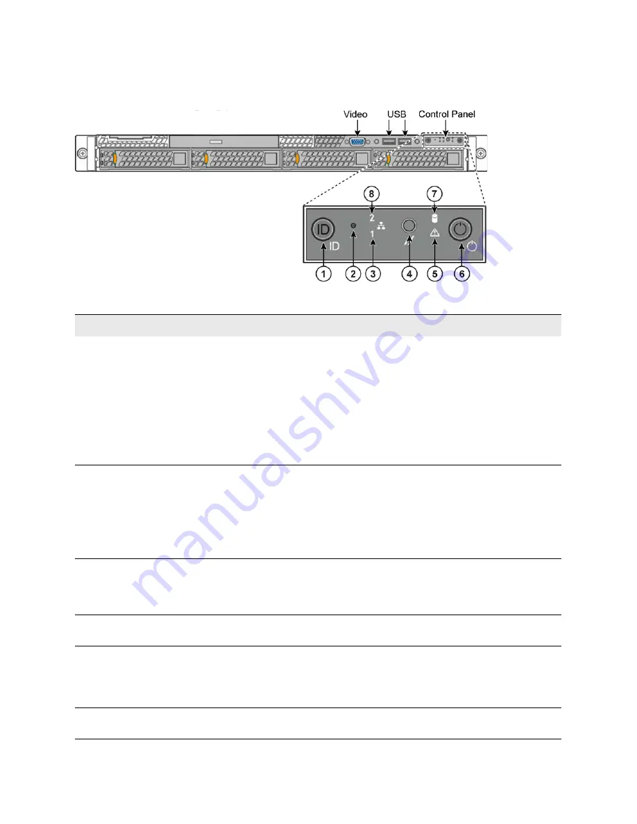
SteelConnect 5030 Gateway front panel LEDs
Figure 1-4. Front Panel LEDs
This table describes the LEDs for the control panel on the SteelConnect SDI-5030 gateway.
Label
Control panel descriptions
LED description
1
System ID button with
integrated LED
Maintenance = blue.
Turns the integrated ID LED and the blue server board ID LED on and
off. The ID LED identifies the gateway for maintenance when installed
in a rack of similar appliances. You can also turn on and turn off the
ID LED remotely by using the Intelligent Platform Management
Interface (IPMI) chassis identify command which causes the LED to
blink for 15 seconds.
A duplicate system ID LED is on the back of the gateway to the left of
the video port.
2
NMI button (recessed, tool
required for use)
Puts the gateway in a halt state and issues a nonmaskable interrupt
(NMI). This state helps when performing diagnostics for a given issue
where a memory download is necessary to determine the cause of
the problem. To prevent an inadvertent system halt, the NMI button
is located behind the front control panel faceplate and is only
accessible with the use of a small tipped tool such as a pin or paper
clip.
3
Port 6 activity LED
Maps to port 6 on the rear panel.
Link = green.
Activity = blinking green. The blink rate is consistent with the amount
of network activity.
4
System cold reset button
(recess, tool required for use)
Reboots the gateway.
5
System status LED
Shows the current health of the server system.
Healthy = green.
Degraded = yellow.
Critical = blinking yellow.
6
Power button with integrated
LED
System on = green.
System off = no light.


