


Page 8
VWP 160-3 / 250-3
➝
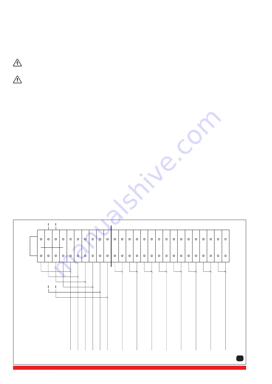
without fan motor and operating thermostat
11
1
2
3
4
5
6
7
8
9
10 11 12 13 14 15 16 17 18 19 20 21 22 23 24 25 26
X1
Suction valve
Bleeding valve
V
alve flushing unit
V
alve sealing gas
Reserve
Reserve
Safety ther
mostat
Operating ther
mostat
Level pr
e-separator
Level flushing liquid
Level cooling water
Level bearing ND
Level bearing MD
Level bearing HD
5.2 Electrical installation
5.2.1 General (see data sheet D 221)
The electrical data can be found on the data plate (N) or the motor data plate. The motors correspond to DIN / VDE 0530 and have
IP 54 protection and insulation class B or F. The connection diagram can be found in the terminal box on the motor. Check the
electrical data of the motor and the control gear for compatibility with your available supply (voltage, frequency, permissible current
etc.). Connect the motor to the incoming supply. It is advisable to use thermal overload motor starters to protect the motor and
wiring. All cabling used on starters should be secured with good quality cable clamps.
We recommend that motor starters should be used that are fitted with a time delayed trip resulting from running beyond the
amperage setting. When the unit is started cold overamperage may occur for a short time.
The electrical installation may only be made by a qualified electrician under the observance of EN 60204. The main
switch must be provided by the operator.
5.2.2 Approximate values for setting motor overload protection
The approximate values for setting motor overload protection should be obtained from the motor manufacturer or
motor nameplate.
5.2.3 Electrical connection
The electrical connections for the control equipment are located in a junction box. The motors may be connected at this junction
box or separately according to local regulations. The terminal strips are numbered and correspond to the control devices (see
wiring diagram pict. 11). We recommend this layout arrangement is adhered to in the event of re-fitting or repairing devices.
5.2.4 Junction box layout radiator cooled version
Fresh water cooling version
➝
without fan motor and operating thermostat


