


Page 6
8
3.4.4 Lubrication
The INOVAC vacuum pump is a dry running pump and
consequently the only lubrication to the stages is to the
bearing and gear drive areas. This is by means of splash discs
(see picture 7). Depending upon stage size the total oil fill
quantity, including pipelines and storage reservoir is approxi-
mately 1.3 1 l.
Oil is supplied from the external reservoirs to the stages via
the flange at the A-side. Located on the right hand side of drive
side flange (seen from the drive end) are two oil pipes which
feed the B-side. The lower, larger pipe is the oil supply
(pressure free) and the upper pipe is for equalisation.
The oil reservoir should be changed at approximately every
8000 operating hours or at least yearly.
At a misfunction, which can lead to the intrusion of products in
the bearing rooms, is to be explored the oil on his lubrication
property.
All other bearings are sealed for life requiring no maintenance.
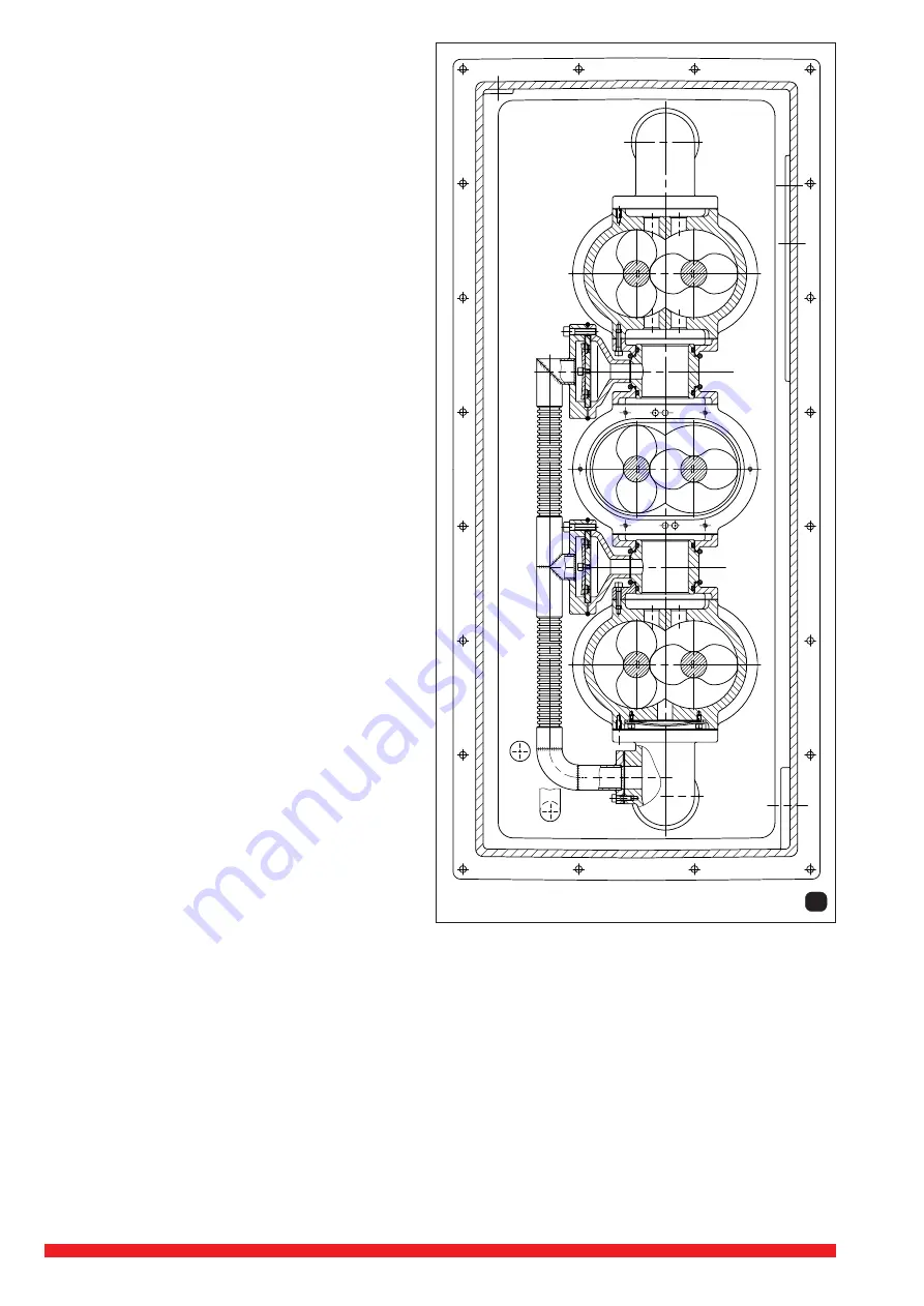
3.4.5 By-pass system (pict. 8)
The by-pass system connects the interstage LP/MP chamber
and the interstage MP/HP chamber with the exhaust duct.
The by-pass system enables the INOVAC vacuum pump to
operate at any suction pressure without overheating which
would result from the over pressure of the MP and HP stages.
The by-pass valves close when the interstage pressures are
lower than the exhaust pressure.
3.4.6 Sealing gas
The INOVAC is supplied as standard with the facility to
pressurise the shaft sealing ring chamber with an inert sealing
gas. This prevents ingress of process material through the
labyrinth piston rings, which could otherwise build up on the
shaft leading to premature wear and damage to sealing rings.
Two thread connections (S
➝
D 221) are provided on the
INOVAC for inlet and outlet of sealing gas which is fed to the
stages via a distribution block and connecting lines. The feed
to the stages is through the drive end flange. The non-drive
end is fed via lines on the left side of the stage (seen from the
drive end).
There occur two kinds of sealing gas operation.
1. Pressurising with sealing gas
The sealing gas system can be pressurised by admitting
gas to the top sealing gas port with the bottom port closed.
The sealing gas then escapes past the labyrinth and piston
ring seals into the compressor chamber, so preventing
process deposits on the seals.
The supply pressure should be 0.3 to 0.4 barG consump-
tion will be approximately 1Nm
3
/hr.
2. Finishing the sealing gas system
If it is thought that deposits may be present between the
sealing rings and the labyrinth. These can be flushed out
before starting the INOVAC. The sealing gas bottom port is
opened for 3-5 minutes, then re-closed. The system then
returns to the pressurised state.


