


Page 11
18
BY
NS
HS
MS
NS
K
2
K
3
K
1
Y
4
K
4
U
1
16
17
V
4
H
4
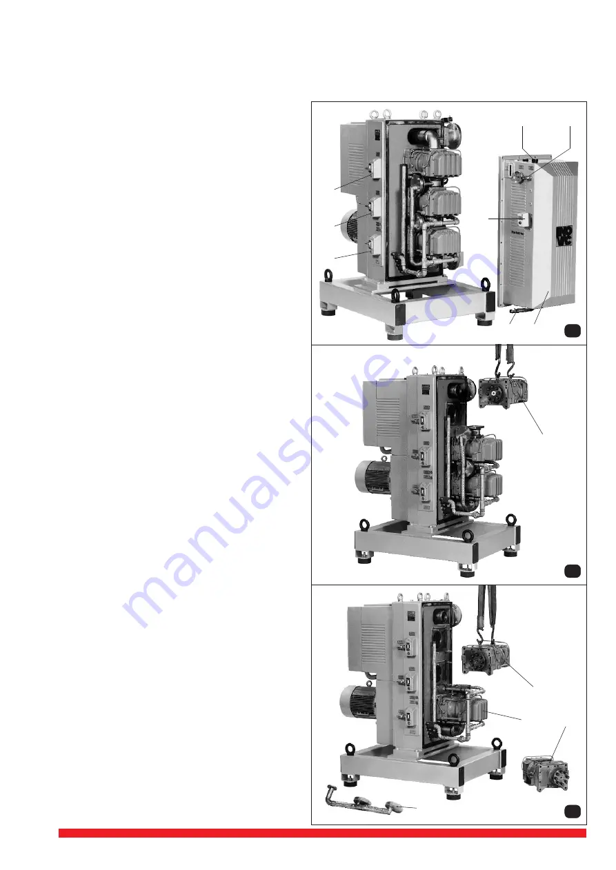
8.3 Exchanging stages
8.3.1 Disassembly and assembly of cooler housing (pict. 16)
Switch off the pump and vent to atmospheric pressure. Open the de-aeration screw (H
4
) for venting the cooler housing (Y
4
) drain
the coolant by opening the drain valve (K
4
). On the external cooled version make sure the coolant entry is closed off. Remove
the cable from the level switch (V
4
) after loosening terminal screw connection on this switch. Remove the safety thermostat (U
1
)
from the cooler housing. Screw in 2 lifting eyes and support the cooler housing using an appropriate tackle and crane. Loosen
and remove the flange screws and pull away the cooler
housing (Y
4
). Assembly is carried out in reserve order. Prior
to assembly, check the sealing of the cooler housing as well
as the thermostat sealing and replace them if necessary.
Before use charge the cooling system with coolant accord-
ing to chapter 6.
8.3.2 Stage change (pict. 16, 17 and 18)
Drain the bearing oil of the stages by opening the plugs (K
1,
K
2,
K
3
). Remove the by-pass system (BY) after having
removed the flange screws on both the valve housing
covers and the connection flange of the outlet conduit.
Please make sure that neither the flange surfaces or the
valves themselves are damaged by the valve body.
Disassemble the vacuum pipe on the LP stage (NS) support
the stage by suitable tackle and crane. Remove the flange
bolts securing the LP stage and loosen the stage by gently
prising away from the centre ring and the drive coupling half.
Remove the intermediate flange on the NP stage (MS).
Removing the MP stage (HS) is carried out in the same
manners as with LP stage.
Assembly of the stages is in reverse order. Prior to re-fitting
the individual sealings should be checked and replaced as
necessary. After re-fitting the stages fill the bearing oil (see
chapter 7 and 9.5) check all connections for possible leak-
age. Mount the cooler housing (see chapter 8.3.1). The
stages themselves can be checked and repaired at an
authorised Rietschle service centre, therefore they should
be returned with the appropriate Health and Safety certifi-
cate.
8.3.3 Commissioning
As regards commissioning please refer to chapter 7.
8.4 Trouble shooting
The optional control system when operating the pump
should be to either give a clear warning or switch off the
pump in a controlled manager when one of the safety
devices has been activated.
8.4.1 Shortage of cooling liquid
Check and top up the level of coolant according to chap-
ter 6.
8.4.2 Shortage of oil
Check and top up the oil level according to chapter 8.1.
8.4.3 Running over amperage
• Check for excessive bearing oil, reduce to normal level
if appropriate.
• Check back pressure in the exhaust pipework, clean
the exhaust air passage or knock out pots, condensers
as necessary.
• By turning the fan of the motor check that the stages and
pump are free to turn.
In case of resistance change and clean each vacuum
stages.
8.4.4 Poor vacuum levels
• Check vacuum at the inlet of the pump, clean the filter
if necessary.
• Check back pressure in the exhaust pipework (exhaust
back pressure may not climb over 0,3 bar).
• Check the belt connection of the HP, MP, and LP stages
(see chapter 8.2.).


