Page 3
1. Introduction
To prevent contamination from possible dangerous sub-
stances contained in the process, the exhaust outlet must
always be connected to an appropriate emission control
system.
All units being returned to our works for mainte-
nance or any other reason must be free of harmful
and dangerous material. A health and safety certificate
should always be provided.
The customer has the responsibility for providing and check-
ing explosion proof safety requirements for the total site in
which vacuum pumps are used.
An appropriate agreement should be obtained from the local
licensing authorities.
2. Application
The INOVAC vacuum pumps are particularly suitable for the
handling of extremely humid gases. These pumps have a
high water vapour tolerance.
The ambient temperatures may be between 5 and
40° C. The suction temperatures should not exceed
60° C. For temperatures out of this range please contact
your supplier.
Liquid slugs and solids cannot be handled by
INOVAC.
Handling of explosive gases or vapours only on request
with our company.
For installations that are higher than 1000 m sea
level there will be a loss in capacity. For further
advice please contact your supplier.
The standard versions may not be used in hazardous areas.
Special versions with Ex-proof motors can be supplied.
All applications where an unplanned shut down of
the pump could possibly cause harm to persons or
installations, then the corresponding safety backup sys-
tems must be installed.
3. Design
The INOVAC is a 3 stage dry running and non-contact
vacuum pump of modular design. The INOVAC is available
in three sizes i.e. 160, 250 and 400 m
3
/hr.
3.1 Construction
With the design of INOVAC the main components are grouped
into four sections:
Drive motor • Power transmission • Vacuum cylinders
• Cooling
The reason for separation and the resulting advantages are:
1. Optimum ease of servicing in case of a stage failure:
• quick exchange of the pump stages without removing
the pump from site
• the vacuum and exhaust pipework need not be re-
moved
• the drive or power transmission parts need not be
touched
• no adjustment or alignment operations are neces-
sary due to the flange connection of the stages
2. Short down time can be achieved (approximately 3
hours) in the event of failure of a pumping stage.
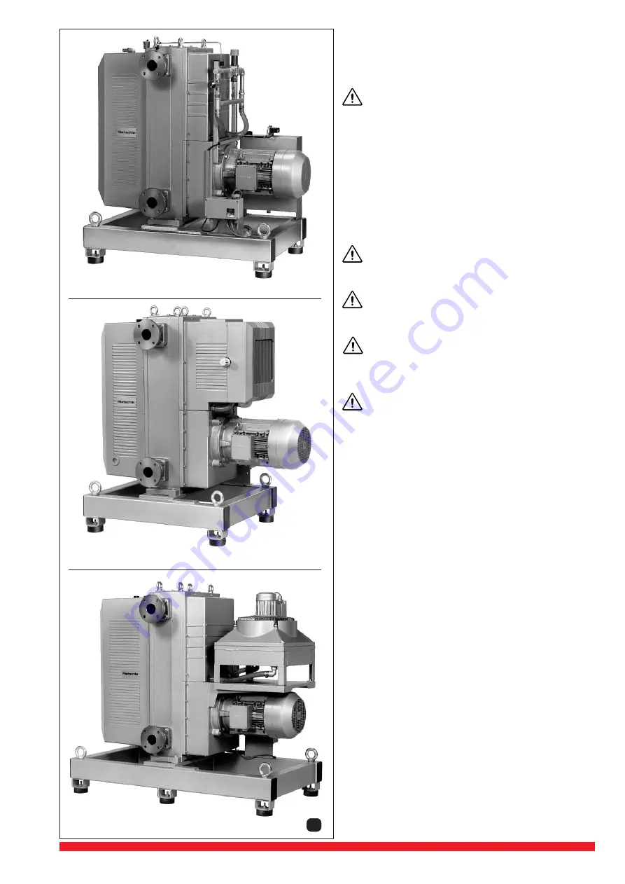
VWP 160-3 / 250-3
with external cooling
VWP 160-3 / 250-3
with closed circulation cooling
VWP 400-3
with closed circulation cooling
1


