


Page 5
3.4 INOVAC individual components
3.4.1 Drive
The INOVAC vacuum pump is driven by a
flanged electric motor, normally the stand-
ard drive supplied with a basic design is
400/690 V, 50 Hz, IP 54, 1450 rpm, B 5
flange:
- VWP 160-3
7.5 kW
- VWP 250-3
7.5 kW
- VWP 400-3
11 kW
There is no problem to fit other types of
electric motors, including explosion proof
and increased safety models.
3.4.2 Power transmission (pict. 6)
The HP stage is directly driven by the drive
motor. The LP stage, MP stage and cooling
water pump and fan are driven by anti-
static flat belts from the HP stage.
The drive motor and the stages are con-
nected to the flat belt drive using pin and
rubber bush couplings.
At the VWP 400-3 the cooling water fan are
driven by an own motor.
VWP 160-3 / 250-3
VWP 400-3
6
A-side
B-side
7
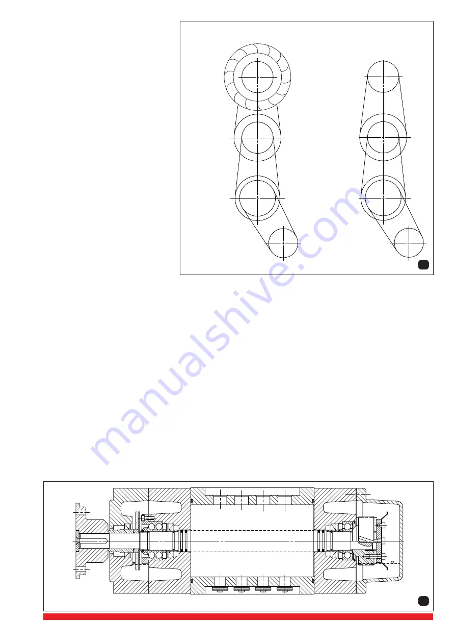
3.4.3 Compressor stages (pict. 7)
The three compressor stages of the INOVAC consist of the casing (GGG-40), two end covers (DE fixed bearing, NDE floating
bearing, material GGG-40), two rotors (GGG-40), the synchronising drive gears, the bearing and the sealing systems. In addition
there are valves in the exhaust side of the MP and HP stages.
The rotors of all three stages are the same length as are the casings of the MP and HP stages. The casing of the LP stage is
somewhat shorter due to lower heat of compression.
In both end covers the compression chamber is sealed from the bearing housing by a labyrinth seal consisting of two piston rings
(PTFE). In addition a shaft sealing ring (PTFE) running on a hardend pressed on shaft sleeve prevents bearing oil from entering
the labyrinth seal. Furthermore it is possible to connect sealing gas between the shaft oil seal and the piston ring labyrinth seal
to prevent any possibility of leakage from the compression chamber to the seal area.
The fixed bearing is a twin deep groove ball bearing and the floating bearing is a single deep grove ball bearing. Both bearings
are lubricated with oil contained within the bearing housing by means of a splash disc. On the A-side the discs are attached to
the rotor shaft using spacer rings, and on the B-side they are mounted on the synchronising gear so as to lubricate the gear and
the bearing at the same time.
The synchronisation of the rotors is adjusted by means of a conical clamping arrangement of the helical cut synchronising gears.
The drive end bearing housing is sealed by means of a further sealing ring running on a pressed-on shaft sleeve. The non-drive
end is closed by an bearing cover (GGG-40). The end covers are bolted to the rotor casing and are fitted with a PTFE encapsulated
viton O-ring.
The stages and the connections between them and the by-pass system are designed for a hydraulic test of 10 bar.
MP stage
HP stage
(drive)
LP stage
and cooling
fan
HP stage
(drive)
Cooling circulation pump
LP stage
Cooling circulation
pump
MP stage


