


Page 10
7. Initial Operation (see data sheet D 221)
Warning –> Start-up with pipework
At start-up, severe damage may occur if there is debris in the pipework.
We therefore recommend a vacuum tight inlet filter of 5 micron rating is installed for start-up.
The pump will normally be delivered with the bearing oil reservoirs filled but these should be checked before first start up. The
correct level is in the middle of the sight glass (I
1
, I
2
, I
3
pict. 2).
The oil reservoirs will normally be supplied with oil level switches (V
1
, V
2
, V
3
pict. 2) which will prevent start up or shut the pump
down, in the event of low level.
The pump should be started and stopped momentarily to check the direction of rotation (see direction arrow O).
NOTE! When handling humid or aggressive gases the pump must be operated before and after the process against
a closed inlet, but with an air bleed into the pump. This pre and post run operation should be carried out for 20-
30 minutes.
Pre-run should ensure that the pump reaches the appropriate operating temperature so that condensation of the pumped gases
is avoided within the pump chambers.
7.1 Potential risks for operating personnel
Noise Emission: The worst noise levels taking into consideration direction and intensity measured according to DIN 45635 part
3 (as per 3. GSGV), are shown in chapter 9.2. When working permanently in the vicinity of an operating pump, we recommend
wearing ear protection to avoid any damage to hearing.
8. Maintenance
When maintaining these units and having such situations where personnel could be hurt by moving parts or by
live electrical parts the pump must be isolated by totally disconnecting the electrical supply. It is imperative that
the unit cannot be re-started during the maintenance operation.
Do not work a pump that is at its normal operating temperature as there is a danger from hot parts, hot lubricant or hot
coolant.
8.1 Oil lubrication
8.1.1 Bearing oil:
Please make sure that there is always sufficient bearing oil in
the oil tanks (1,2, 3).
Oil change interval: We recommend that the oil should be
changed completely after 8,000 operating hours or at least
yearly.
The viscosity must correspond to ISO-VG 100 according to
DIN 51 519.
We recommend the following oil brands: Bechem VBL 100,
BP Energol RC 100, Esso rotary oil 100, Mobil vacuum pump
oil heavy, Shell Tellus oil C 100 or Aral Motanol HK 100.
8.1.2 Changing the bearing oil (see D 221))
Oil drain:
LP stage (K
1
), MP stage (K
2
), HP stage (K3).
Oil fill port:
LP stage (H
1
), MP stage (H
2
), LP stage (H3).
The waste oil removal should be done according to
environmental regulations. In case of lubricant
change please empty oil tank totally.
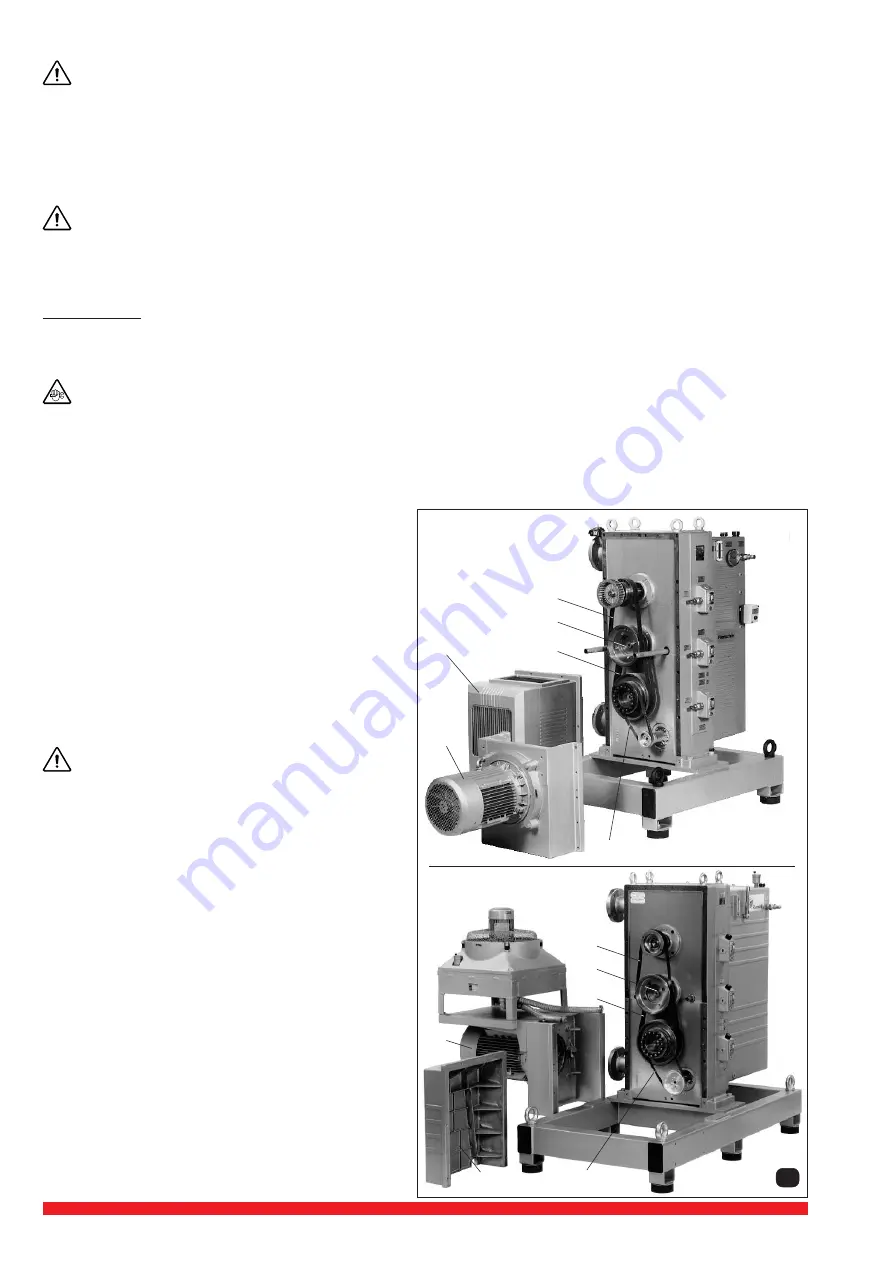
8.2 Flat belt (pict. 15)
8.2.1 Maintenance
The flat belts for the drive HP/MP stage (R
1
), MP/LP stage
(R
2
), motor/cooling liquid pump (R
3
) do not require any
maintenance and need not be pretensioned.
8.2.2 Flat belt change interval
We would recommend the changing of the Flat Belt (R
1,
R
2,
R
3
)
after 15,000 operating hours.
8.2.3 Disassembly/assembly of flat belts
Drain off coolant!
Loosen the screws and push the drive motor (m) as far back
as possible and put aside. Remove the cover (n) after loosen
the screws. Remove the belt from the drive motor/cooling
water pump (R
3
), remove the belts of the MP / LP stage (R
2
),
remove the belt discs (RS) on MP stage by loosening the
appropriate screws. Take off the HP / MP stage belt (R
1
).
The new belt can be assembled in the reverse order, the new
belts need not be pretensioned after assembly.
For assembly and disassembly a special belt tool is required.
n
m
R
1
RS
R
2
R
3
VWP 160-3 / 250-3
15
R
3
m
n
R
1
RS
R
2
VWP 400-3


