Riello 966 T Installation, Use And Maintenance Instructions Download Page 33

33

BRENNERBETRIEB

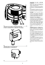
ANFAHREN DES BRENNERS (A) - (B)

Startphasen mit progressiven Zeitangaben in
Sekunden:
• Verschluß der TL-Fernsteuerung.

Nach etwa 3s:

0 s : 

Das Programm des elektrischen

Steuergeräts beginnt.

2 s : 

Anfahren Gebläsemotor. Start des Stel-

lantriebs (12), Öffnung der Luftklappe in 1.
Stufe.

3 s : 

Einschalten des Zündtransformators.

Die Pumpe 3) saugt den Brennstoff über die
Leitung 1) und den Filter 2) vom Tank an und
pumpt ihn unter Druck in den Auslaß. Der Kol-
ben 4) geht hoch und der Brennstoff kehrt
über die Leitungen 5)-7) in den Tank zurück.
Die Schraube 6) schließt den Bypass gegen
die Ansaugleitung ab und die unerregten Elek-
troventile 8)-9) und 10) verschließen den Weg
zu den Düsen.

22 s : 

Die Magnetventil 8) und 9) werden

geöffnet. Der Brennstoff tritt zerstäubt aus der
Düse aus und entzündet sich beim Kontakt mit
dem Funken: Flamme 1° Stufe.

29 s: 

Der Zündtransformator schaltet sich aus.

36 s: 

Wenn die Fernsteuerung TR geschlos-

sen ist oder durch eine Überbrückung ersetzt
wurde, öffnet sich das Magnetventil 10) und
der Stellantrieb bringt die Luftklappe auf die 2.
Stufe. Der Anfahrzyklus ist beendet.

DAUERBETRIEB
Anlage mit TR-Fernsteuerung

Nach dem Anfahrzyklus den Wählschalter 0-
Auto-Man


auf Auto stellen; die Steuerung des

Magnetventils der 2° Stufe geht auf die  TR-Fern-
steuerung über, die Temperatur oder den Druck
im Kessel überwacht.
• Wenn die Temperatur oder der Druck bis zur

Öffnung von TR zunimmt, schließt das Magnet-
ventil 10) und der Brenner geht von der 2. zur
1° Funktionsstufe über.

• Wenn Temperatur oder Druck bis zum Ver-

schluß von TR abnimmt, öffnet das Magnet-
ventil 10) und der Brenner geht von der 1. zur
2. Funktionsstufe über, usw.

• Das Anhalten des Brenners erfolgt wenn der

Bedarf an Wärme kleiner als die vom Brenner
in der 1° Stufe gelieferte Menge ist. Die TL-
Fernsteuerung wird geöffnet, die Magnetven-
tile 8)-9) verschließen sich, die Flamme erlischt
augenblicklich. Die Luftklappe des Gebläses
schließt sich vollständig.

Anlage ohne TR, mit Brücke.

Das Anfahren des Brenners erfolgt wie oben
beschrieben. Wenn danach die Temperatur oder
der Druck bis zum Öffnen von TL zunimmt, geht
der Brenner aus (Linie A-A des Diagramms).

MANGELNDE ZÜNDUNG

Wenn der Brenner nicht zündet, erfolgt die
Störabschaltung des Brenners innerhalb von 5 s
ab dem Öffnen des Magnetventils der 1. Stufe
und 30 s nach dem Verschluß des TL.
Die rote LED am elektrischen Steuergerät
leuchtet auf.

AUSGEHEN WÄHREND DES BETRIEBS

Wenn die Flamme während des Betriebs erl-
ischt, schaltet sich der Brenner innerhalb von 1 s
aus und versucht erneut anzufahren, wobei die
Phase des Anfahrens wiederholt wird.
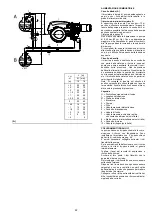
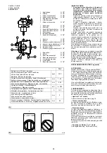
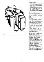
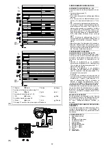
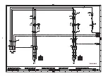
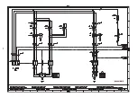
HYDRAULIKSCHALTPLAN

1

Ansaugung Pumpe

2

Filter

3

Pumpe

4

Druckregler

5

Rücklaufleitung

6

By-pass Schraube

7

Rücklauf Pumpe

8

Sicherheitsmagnetventil

9

Ventil 1. Stufe

10 Ventil 2. Stufe

11 Filter

M

Manometer

V

Vakuummeter

BURNER OPERATION

BURNER STARTING


(A) - (B)

Starting phases with progressive time intervals
shown in seconds:
• Control device TL closes.

After about 3s:

0 s : 

The control box starting cycle begins.

2 s : 

The fan motor starts. Servomotor (12)

starts, air damper opens in 1

st

 stage position.

3 s : 

The ignition transformer is connected.

The pump 3) sucks the fuel from the tank
through the piping 1) and the filter 2) and
pumps it under pressure to delivery. The pis-
ton 4) rises and the fuel returns to the tank
through the piping 5) - 7). The screw 6) closes
the by-pass heading towards suction and the
solenoid valves 8) - 9) - 10), de-energized,
close the passage to the nozzles.

22 s : 

Solenoid valves 8) and 9) open and the

fuel is sprayed out through the nozzle, igniting
when it comes into contact with the spark. This
is the 1st stage flame.

29 s: 

The ignition transformer switches off.

36 s: 

If the control device TR is closed or has

been replaced by a jumper wire, the 2nd stage
solenoid valve 10) opens and the servomotor
moves the air damper to 2

nd

 stage position

.

The starting cycle comes to an end.

STEADY STATE OPERATION
System equipped with one control device TR

Once the starting cycle has come to an end,set
0-auto-man


selector to auto the command of the

2nd stage solenoid valve passes on to the con-
trol device TR that controls boiler temperature or
pressure.
• When the temperature or the pressure increas-

es until the control device TR opens, solenoid
valve 10) closes, and the burner passes from
the 2nd to the 1st stage of operation.

• When the temperature or pressure decreases

until the control device TR closes, solenoid
valve 10) opens, and the burner passes from
the 1st to the 2nd stage of operation, and so on.

• The burner stops when the demand for heat is

less than the amount of heat delivered by the
burner in the 1st stage. In this case, the control
device TL opens, and solenoid valves 8)-9)
close, the flame immediately goes out. The
fan's air gate valve closes completely.

Systems not equipped with control device
TR (jumper wire installed)

The burner is fired as described in the case
above. If the temperature or pressure increase
until control device TL opens, the burner shuts
down (Section A-A in the diagram).

FIRING FAILURE

If the burner does not fire, it goes into lock-out with-
in 5 s of the opening of the 1st nozzle valve and 30
s after the closing of control device TL. 
The control box red pilot light will light up.

UNDESIRED SHUTDOWN DURING OPERA-
TION

If the flame goes out during operation, the burner
shuts down automatically within 1 second and
automatically attempts to start again by repeat-
ing the starting cycle.

HYDRAULIC SYSTEM LAYOUT

1

Pump  suction

2

Filter

3

Pump

4

Pressure governor

5

Return pipe

6

By-pass screw

7

Pump  return

8

Safety solenoid

9

1st stage valve

10 2nd stage valve
11 Filter
M

Pressure gauge

V

Vacuometer

FONCTIONNEMENT BRULEUR

DEMARRAGE BRULEUR


(A) - (B)

Phases de démarrage avec temps progressifs
en s.:
• Fermeture télécommande TL.

Après environ 3s:

0 s : 

Le cycle de démarrage du coffret de

sécurité est commencé.

2 s : 

Démarrage moteur ventilateur. Démar-

rage du servomoteur (12), ouverture du volet
d’air en 1

ère

 allure.

3 s : 

Insertion transformateur d'allumage.

La pompe 3) aspire le combustible de la cuve
à travers le conduit 1) et le filtre 2) et le refoule
sous pression. Le piston 4) se soulève et le
combustible revient dans la cuve par les
tuyaux 5)-7). La vis 6) ferme le by-pass côté
aspiration et les électrovannes 8)-9)-10), dés-
excitées, ferment la voie côté les gicleurs.

22 s : 

Les électrovannes 8) et 9) s'ouvrent. Le

combustible  sort atomisé par le gicleur et au
contact de l'étincelle, s'allume: flamme 1re
allure.

29 s: 

Le transformateur d'allumage s'éteint.

36 s: 

Si la télécommande TR est fermée ou est

remplacée par un pont, l'électrovanne 10)
s’ouvre et le servomoteur met le volet d’air en
2

ème

 allure. Le cycle de démarrage se termine.

FONCTIONNEMENT DE REGIME
Installation munie d'une télécommande TR

Une fois le cycle de démarrage terminé, mettre
le sélecteur 0-auto-man sur automatique la com-
mande de l'électrovanne de 2

ème

 allure passe à

la télécommande TR qui contrôle la température
ou la pression dans la chaudière.
• Quand la température, ou la pression, aug-

mente jusqu'à l'ouverture de TR, l'électrovanne
10) se ferme et le brûleur passe de la 2

ème

 à la

1

ère

 allure de fonctionnement.

• Quand  la température, ou la pression, diminue

jusqu'à la fermeture de TR, l'électrovanne 10)
s'ouvre et le brûleur passe de la 1

ère

 à la 2

ème

allure de fonctionnement.
Et ainsi de suite.

• L'arrêt du brûleur a lieu quand la demande de

chaleur est inférieure à celle fournie par le
brûleur à la 1

ère

 allure. La télécommande TL

s'ouvre et  les électrovannes 8)-9) se ferment,
la flamme s'éteint immédiatement. Le volet du
ventilateur se ferme complètement.

Installation sans TR, remplacée par un pontet

Le démarrage du brûleur se fait comme dans le
cas précédent. Par la suite, si la température, ou la
pression, augmente jusqu'à l'ouverture de TL, le
brûleur s'éteint (segment A-A dans le diagramme).

ABSENCE D'ALLUMAGE

Si le brûleur ne s'allume pas, on a le blocage
dans un délai de 5 s à compter de l'ouverture de
l'électrovanne de 1

ère

 allure et de 30 s après la

fermeture de TL.
Le voyant du coffret de sécurité s'allume.

ARRÊT DU BRÛLEUR AU COURS DU
FONCTIONNEMENT

Si la flamme s'éteint au cours du fonctionne-
ment, le brûleur s'arrête dans un délai d'une
seconde et effectue un essai de redémarrage
avec répétition du cycle de départ.

SCHEMA HYDRAULIQUE 

1

Aspiration pompe

2

Filtre

3

Pompe

4

Régulateur de pression

5

Conduit de retour

6

Vis by-pass

7

Retour pompe

8

Electrovanne de sécurité

9

Electrovanne 1ère allure

10 Electrovanne 2ème allure
11 Filtre
M

Manomètre

V

Vacuomètre

Summary of Contents for 966 T

Page 1: ...our l installation l utilisation et l entretien 2916108 12 01 2017 Bruciatori di gasolio Heiz lbrenner Light oil burners Br leurs fioul domestique Funzionamento bistadio Zweistufiger Betrieb Two stage...

Page 2: ...Leiter der Abteilung Forschung und Ent wicklung RIELLO S p A Gesch ftsleitung Brenner Ing U Ferretti Ing F Comencini Manufacturer s Declaration RIELLO S p A declares that the following products compl...

Page 3: ...hen Abhilfen 39 Anhang Schaltplan 42 D CONTENTS Technical data page 8 Electrical data 8 List of available models 9 Accessories 9 Burner description 13 Description of panel board 13 Weight 15 Standard...

Page 4: ...Funzionamento Intermittente min 1 arresto in 24 ore Bistadio alta e bassa fiamma e monostadio tutto niente Pompa portata a 20 bar kg h campo di pressione bar temperatura combustibile C 380 7 40 140 U...

Page 5: ...asolio Metano Regolazione Testa TC Testa standard TL Testa lunga Sistema di controllo fiamma FS1 FS2 Standard 1 stop ogni 24 h Funzionamento continuo 1 stop ogni 72 h Alimentazione elettrica del siste...

Page 6: ...6 cSt Betrieb Aussetzend min 1 Halt in 24 Std Zweistufig hohe und niedrige Flamme einstufig alles nichts Pumpe F rdermenge bei 20 bar kg h Druckbereich bar Brennstofftemperatur C 380 7 40 140 D sen St...

Page 7: ...instellung Flammkopf TC Standardkopf TL Verl ngerter Kopf Flammen berwachung FS1 FS2 Standard intermittierend min 1 Abschaltung in 24 Std Dauerbetrieb 1 Abschaltung in 72 Std Stromversorgung des Syste...

Page 8: ...6 cSt Operation Intermittent min 1 stop in 24 hours Two stage high and low flame and single stage all nothing Pump delivery at 20 bar kg h pressure range bar fuel temperatur C 380 7 40 140 Nozzles num...

Page 9: ...Methane Setting Head TC Standard head TL Extended head Flame control system FS1 FS2 Standard 1 stop every 24 h Continuos working 1 stop every 72 h Electrical supply to the system 3 400 50 3 230 50 Aux...

Page 10: ...t 20 C mm2 s max 6 1 5 E 6 cSt Fonctionnement Intermittent 1 arr t min en 24 heures 2 allures flamme haute et basse et une allure tout rien Pompe d bit 20 bar kg h plage de pression bar temp rature co...

Page 11: ...thane R gulation E Came lectronique EV Came lectronique et moteur fr quence variable avec Variateur de fr quence T te TC T te standard TL T te longue Syst me de contr le flamme FS1 FS2 Standard 1 arr...

Page 12: ...ausiliari 7 Segnalazione luminosa intervento rel ter mico motore 8 Segnalazione luminosa blocco bruciatore e pulsante di sblocco 9 Apparecchiatura elettrica 10 Avviatore stella triangolo solo RL 400 B...

Page 13: ...ee contacts 2 Ignition transformer 3 Stop push button 4 Dial for off automatic manual 5 1st 2nd stage selector 6 Signal light for auxiliary voltage 7 Motor thermal cutout tripped warning light 8 Signa...

Page 14: ...cative L ingombro del bruciatore riportato in fig B Tener presente che per ispezionare la testa di combustione il bruciatore deve essere aperto ruotando la parte posteriore sulla cerniera L ingombro d...

Page 15: ...e burner flange to the boiler M 18 x 70 1 Instruction booklet 1 Spare parts list MAX DIMENSIONS B Approximate measurements The maximum dimensions of the burner are given in B Bear in mind that inspect...

Page 16: ...della camera di combustione nettamente pi piccole di quelle indicate dal diagramma B consultare i costruttori CALDAIA DI PROVA B I campi di lavoro sono stati ricavati in speciali caldaie di prova sec...

Page 17: ...pe approved and its combustion chamber dimensions are similar to those indicated in diagram B If the burner must be combined with a boiler that has not been CE type approved and or its com bustion cha...

Page 18: ...a portata del bruciatore in 2 stadio Le portate del 1 e del 2 stadio devono essere comprese tra i valori indicati a pag 4 Utilizzare ugelli con angolo di polverizzazione 60 alla pressione consigliata...

Page 19: ...y unscrewing the two connectors 3 Note While unscrewing some fuel may leak out Extract the internal part 5 of the combustion head CHOICE OF NOZZLES FOR 1ST AND 2ND STAGE Both nozzles must be chosen fr...

Page 20: ...iave L ugello per il 1 stadio di funzionamento quello sottostante gli elettrodi di accensione fig C POSIZIONE ELETTRODI C Controllare che gli elettrodi siano posizionati come in fig C REGOLAZIONE TEST...

Page 21: ...ing the nozzle sealing seat The nozzles must be screwed into place tightly but not to the maximum torque value provided by the wrench The nozzle for the 1st stage of operation is the one lying beneath...

Page 22: ...to con la serie termostatica il quale fornir il consenso al bruci atore solo in presenza di pressione Legenda H Dislivello pompa valvola di fondo L Lunghezza tubazione Diametro interno tubo 1 Bruciato...

Page 23: ...ote We advise you to fit on the loop circuit an oil pressure switch connected to the thermo static series It will provide clearance to the burner only if there ispressure Key H Pump Foot valve height...

Page 24: ...ustione all uscita della caldaia ed intervenire sui punti che seguono Ugelli di 1 e 2 stadio Vedere informazioni riportate a pag 18 Testa di combustione La regolazione della testa gi effettuata a pag...

Page 25: ...ng other wise the pump will seize Whenever the length of the suction piping exceeds 20 30 meters the supply line must be filled using a separate pump BURNER CALIBRATION light oil operation FIRING Set...

Page 26: ...anda aria in 1 stadio e in preventilazione viene tarata in fab brica sulla posizione di 22 Camma 3 rossa Regola la fine corsa della serranda aria o il fun zionamento in 2 stadio non superando i 90 vie...

Page 27: ...lly closed Cam 2 orange Adjusts the position of the air damper to 1st stage or pre purging factory set to 22 position Cam 3 red Adjusts air damper travel or 2nd stage operation without exceeding 90 fa...

Page 28: ...regolar mente ma al momento dell accensione il brucia tore va in blocco per mancata accensione a causa dell intervento del pressostato olio La regolazione viene effettuata tramite la vite B fig B PRE...

Page 29: ...ow the pump s set ting See table D page 18 it comes with a fac tory setting of 8 bar If pressure is below the pump setting the start up cycle begins as usual but when the burner is to ignite it locks...

Page 30: ...ne rileva lo stato di sporcamento Se invece la causa delle anomalie sta nel condotto di aspirazione controllare che non vi siano filtro di linea sporco o ingresso d aria nel condotto Filtri Controllar...

Page 31: ...s not entering the piping Filters Check the following filter boxes fig A page 22 on line 3 in the pump 2 at the nozzle and clean or replace as required If rust or other impurities are observed inside...

Page 32: ...di funzionamento Quando la temperatura o la pressione diminuisce fino alla chiusura di TR l elettroval vola 10 si apre ed il bruciatore passa dal 1 al 2 stadio di funzionamento E cos via L arresto del...

Page 33: ...ture or pressure When the temperature or the pressure increas es until the control device TR opens solenoid valve 10 closes and the burner passes from the 2nd to the 1st stage of operation When the te...

Page 34: ...funzionamento secondo la codifica indicata nella tabella di pag 38 DIAGNOSTICA SOFTWARE Fornisce l analisi della vita del bruciatore mediante collegamento ottico a PC indicandone ore di funzionamento...

Page 35: ...ken loslassen Die Blinkh ufigkeit gibt die Ursache der Betriebsst rung an nach den Angaben in Tabelle auf Seite 39 SOFTWAREDIAGNOSTIK Liefert eine Analyse des Brennerlebens mittels optischer PC Verbin...

Page 36: ...he malfunction according to the coding system indicated in the table on page 40 SOFTWARE DIAGNOSTICS Reports burner life by means of an optical link with the PC indicating hours of operation number an...

Page 37: ...dans le tableau la page 41 DIAGNOSTIC FOURNI PAR LE LOGICIEL Il d termine l tat du br leur gr ce une interface optique l ordinateur en en indiquant les heures de fonctionnement le nombre et le type d...

Page 38: ...1 ugello 39 1 ugello sporco o deformato Sostituirlo 40 Pressione pompa non adatta Regolarla tra 10 e 14 bar 41 Ugello 1 stadio non adatto al bruciatore o alla caldaia Vedere tabella ugelli ridurre uge...

Page 39: ...mutzt oder deformiert Auswechseln 40 Ungeeigneter Pumpendruck Zwischen 10 und 14 bar einstellen 41 Nicht f r Brenner oder Kessel geeignete D se 1 Stufe Siehe Tab D sen D se der 1 Stufe reduzie ren 42...

Page 40: ...livery 38 1st nozzle is too small flame detachment Increase 1st nozzle delivery 39 1st nozzle dirty or deformed Replace 40 Inappropriate pump pressure Adjust to between 10 and 14 bar 41 1st stage nozz...

Page 41: ...39 1er gicleur sale ou d form Le remplacer 40 Pression pompe inad quate R gler entre 10 et 14 bar 41 Gicleur 1re allure non adapt au br leur ou la chaudi re Voir tableau gicleurs r duire gicleur 1re a...

Page 42: ...n r f rences Schema funzionale Betriebsschema Operational layout Sch ma fonctionnel Schema funzionale RMO 88 Betriebsschema RMO 88 RMO 88 operational layout Sch ma fonctionnel RMO 88 6 Schema funziona...

Page 43: ...43 0 1 2 30 0 0 1 2 30 0 1 2 2 4 4 0 4 0 5 4 6 4 0 4 0 0 4 4 4 4 4 74 7 7 4 4 0 5 4 0 0 0 0 0 0 0 RL 300 B MZ...

Page 44: ...44 0 0 1 2 30 0 0 0 1 2 30 0 1 2 2 4 4 0 4 0 5 4 6 4 0 4 0 0 4 4 4 4 4 74 7 7 4 4 0 5 4 0 0 0 0 0 0 0 0 RL 400 B MZ...

Page 45: ...45 RL 300 B MZ...

Page 46: ...46 RL 400 B MZ...

Page 47: ...47...

Page 48: ...48 RL 300 B MZ...

Page 49: ...49 0 1 1 1 2 3 2 RL 400 B MZ...

Page 50: ...50 01123 0 3 112 01453 6 7 0 3 8 9 0 3 112 01453 6 7 8 9 8 8 9 8 9 76 76 A...

Page 51: ...Connettore sensori fiamma XSM Connettore servomotore V1 Valvola 1 stadio gasolio V2 Valvola 2 stadio gasolio VS Valvola gasolio di sicurezza ZEICHENERKL RUNG SCHEMEN A1 Steuerger t F1 Gebl semotor W r...

Page 52: ...nnector V1 Light oil 1st stage valve V2 Light oil 2nd stage valve VS Light oil safety valve L GENDE SCH MAS ELECTRIQUE A1 Coffret de s curit F1 Relais thermique moteur ventilateur F2 Relais thermique...

Page 53: ......

Page 54: ......

Page 55: ......

Page 56: ...RIELLO S p A I 37045 Legnago VR Tel 39 0442 630111 http www riello it http www riello com Con riserva di modifiche nderungen vorbehalten Subject modifications Sous r serve de modifications...

Reviews: