background image

23

BRENNSTOFFZUFÜHRUNG

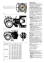
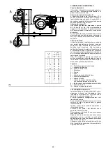
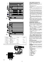
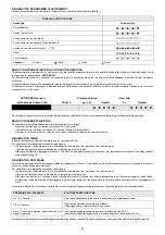
Zweistrangsystem (A)

Der Brenner verfügt über eine selb-
stansaugende Pumpe und kann sich daher,
innerhalb  der Grenzen der seitlich abgebildeten
Tabelle, selbst versorgen.
Tank höher als der Brenner 

A

Die Strecke P sollte nicht höher als  10 m sein,
damit das Dichtungsorgan der Pumpe nicht
überlastet wird, und die Strecke V sollte 4 m
nicht überschreiten, damit die Selbstein-
schaltung der Pumpe auch bei fast leerem Tank
möglich ist.
Tank niedriger 

B

Der Pumpenunterdruck von  0,45 bar (35 cm
Hg) darf nicht überschritten werden. Bei
höheren Unterdruckwerten werden Gase des
Brennstoffs befreit; die Pumpe entwickelt mehr
Geräusche und ihre Haltbarkeit wird beein-
trächtigt.
Es empfiehlt sich, die Rücklaufleitung auf der-
selben Höhe wie die Ansaugleitung ankommen
zu lassen; das Abkuppeln der Ansaugleitung ist
schwieriger.

Kreisschaltung

Sie besteht aus einer Leitung, die von und zum
Tank führt, in der eine Hilfspumpe den Brenn-
stoff unter Druck fließen läßt. Eine Abzweigung
des Kreises speist den Brenner. Diese
Schaltung ist nützlich, wenn die Brennerpumpe
sich nicht selbst speisen kann, weil Abstand
und/oder Höhe vom Tank größer sind als die in
der Tabelle aufgeführten Werte.
Anmerkung: Es empfiehlt sich, einen Öldruck-
wächter in die Kreisschaltung einzuschalten, der
mit der thermostatischen Serie verbunden ist,
die dem Brenner die Freigabe nur bei Vorhan-
densein von Druck liefern wird.

Zeichenerklärung

H = Höhenunterschied Pumpe/Bodenventil
L = Leitungslänge
Ø = Innendurchmesser Leitung
1 = Brenner
2 = Pumpe
3 = Filter
4 = Manuelles Sperrventil
5 = Ansaugleitung
6 = Bodenventil
7 = Manuelles Schnellschließventil mit Fern-

steuerung (nur Italien)

8 = Sperrmagnetventil (nur Italien)
9 = Rücklaufleitung
10 = Rückschlagventil (nur Italien)

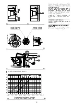
HYDRAULIKANSCHLÜSSE

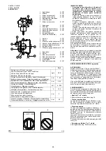
Die Pumpen verfügen über einen Bypass, der
Rücklauf und Ansaugung miteinander verbindet.
Sie sind am Brenner installiert und der Bypass
ist mit der Schraube 6) verschlossen, siehe Plan
S. 44.
Beide Schläuche sind demnach an die Pumpe
anzuschließen.
Wird die Pumpe bei geschlossenem Rücklauf
betrieben und die Bypass-Schraube eingesetzt,
wird sie sofort beschädigt.
Die Verschlußschrauben von den Saug- und
Rücklaufanschlüssen der Pumpe abnehmen.
An deren Stelle die Schläuche mit den beige-
packten Dichtungen einbauen. 
Beim Einbau dürfen diese Schläuche nicht ver-
bogen werden.
Die Schläuche sind so zu führen, daß sie weder
Trittbelastungen noch warmen Kesselteilen aus-
gesetzt werden und daß der Brenner geöffnet
werden kann.
Anschließend das andere Schlauchende mit
den Ansaug - und Rücklaufleitungen durch die
mitgelieferten Nippel verbinden.

FUEL SUPPLY

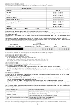
Double-pipe circuit (A)

The burner is equipped with a self-priming pump
which is capable of feeding itself within the limits
listed in the table at the side.
The tank higher than the burner 

A

The distance "P" must not exceed 10 meters in
order to avoid subjecting the pump's seal to
excessive strain; the distance "V" must not
exceed 4 meters in order to permit pump self-
priming even when the tank is almost com-
pletely empty.
The tank lower than the burner 

B

Pump depression values higher than 0.45 bar
(35 cm Hg) must not be exceeded because at
higher levels gas is released from the fuel, the
pump starts making noise and its working life-
span decreases.
It is good practice to ensure that the return and
suction lines enter the burner from the same
height; in this way it will be more improbable that
the suction line fails to prime or stops priming.

The loop circuit

A loop circuit consists of a loop of piping depart-
ing from and returning to the tank with an auxil-
iary pump that circulates the fuel under
pressure. A branch connection from the loop
goes to feed the burner. This circuit is extremely
useful whenever the burner pump does not suc-
ceed in self-priming because the tank distance
and/or height difference are higher than the val-
ues listed in the Table.
Note: We advise you to fit, on the loop circuit, an
oil pressure switch connected to the thermo-
static series. It will  provide clearance to the
burner only if there ispressure.

Key

H = Pump/Foot valve height difference
L = Piping length
Ø = Inside pipe diameter
1 = Burner
2 = Pump
3 = Filter
4 = Manual on/off valve
5 = Suction line
6 = Foot valve
7 = Rapid closing manual valve

remote controlled (Italy only)

8 = On/off solenoid valve (Italy only
9 = Return line
10 = Check valve (Italy only)

HYDRAULIC CONNECTIONS

The pumps are equipped with a by-pass that
connects return line and suction line. The
pumps are installed on the burner with the by-
pass closed by screw 6), see diagram page 44.
It is therefore necessary to connect both hoses
to the pump.
The pump will break immediately if it is run with
the return line closed and the by-pass screw
inserted.
Remove the plugs from the suction and return
connections of the pump.
Insert the hose connections with the supplied
seals into the connections and screw them
down. 
Take care that the hoses are not stretched or
twisted during installation.
Install the hoses where they cannot be stepped
on or come into contact with hot surfaces of the
boiler and where they do not hamper the open-
ing of the burner.
Now connect the other end of the hoses to the
suction and return lines by using the supplied
nipples.

ALIMENTATION COMBUSTIBLE

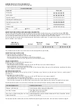
Circuit à double tuyau (A)

Le brûleur est muni d'une pompe à aspiration
automatique et par conséquent, dans les limites
indiquées dans le tableau ci-contre, il est en
mesure de s'alimenter tout seul.
Cuve située plus haut que le brûleur 

A

Il est opportun que la cote P ne dépasse pas 10
m pour ne pas trop solliciter l'organe
d'étanchéité de la pompe et que la cote V ne
dépasse pas 4 m pour permettre l'auto-
amorçage de la pompe même avec la cuve
presque vide.
Cuve située plus bas que le brûleur 

B

On ne doit pas dépasser une dépression de
0,45 bar (35 cm Hg) dans la pompe. Avec une
dépression supérieure, des gaz se dégagent du
combustible; la pompe devient bruyante et sa
durée de vie diminue.
Nous conseillons de faire arriver le tuyau de
retour à la même hauteur que le tuyau d'aspira-
tion;   le désamorçage du tuyau d'aspiration est
plus difficile.

Circuit en anneau

Il est constitué d'un conduit partant de la cuve et
y revenant dans lequel une pompe auxiliaire fait
circuler le combustible sous pression. Une déri-
vation de l'anneau alimente le brûleur. Ce circuit
est utile quand la pompe du brûleur ne parvient
pas à s'auto-alimenter parce que la distance et/
ou la différence de niveau avec la cuve sont
supérieures aux valeurs données dans le tab-
leau.
Remarque

Il est conseillé de monter un

pressostat huile relié à la série thermostatique
sur le circuit en anneau. Ce pressostat ne
donnera l’accord au brûleur qu’en cas de
pression dans le circuit.

Légende

H = Diff. niveau pompe-clapet de pied
L = Longueur tuyau
Ø = Diamètre interne tuyau
1 = Brûleur
2 = Pompe
3 = Filtre
4 = Soupape manuelle d'arrêt
5 = Conduit d'aspiration
6 = Clapet de pied
7 = Vanne manuelle à fermeture rapide

avec commande à distance (uniquement
pour l'Italie)

8 = Electrovanne d'arrêt (uniquement pour

l'Italie)

9 = Conduit de retour
10 = Vanne de retenue (uniquement pour l'Italie)

RACCORDEMENTS HYDRAULIQUES

Les pompes ont un by-pass qui met en commu-
nication le retour avec l'aspiration. Elles sont
installées sur le brûleur avec le by-pass fermé
par la vis 6), voir schéma page 44.
Il faut donc raccorder les deux flexibles à la
pompe.
Si on fait fonctionner la pompe avec le retour
fermé et la vis de by-pass insérée, la pompe
s'abîme immédiatement.
Retirer les bouchons des prises de raccorde-
ment d'aspiration et de retour de la pompe.
Visser à leur place les flexibles avec les joints
de série. 
Lors du montage, ces flexibles ne doivent pas
être soumis à des torsions.
Disposer les flexibles de manière à éviter de les
écraser avec le pied et qu'ils soient en contact
avec des parties chaudes de la chaudière. Faire
en sorte qu'ils puissent permettre l'ouverture du
brûleur.
Raccorder ensuite l'autre extrémité des flexibles
aux conduits d'aspiration et de retour à l'aide
des raccords de série.

Summary of Contents for 966 T

Page 1: ...our l installation l utilisation et l entretien 2916108 12 01 2017 Bruciatori di gasolio Heiz lbrenner Light oil burners Br leurs fioul domestique Funzionamento bistadio Zweistufiger Betrieb Two stage...

Page 2: ...Leiter der Abteilung Forschung und Ent wicklung RIELLO S p A Gesch ftsleitung Brenner Ing U Ferretti Ing F Comencini Manufacturer s Declaration RIELLO S p A declares that the following products compl...

Page 3: ...hen Abhilfen 39 Anhang Schaltplan 42 D CONTENTS Technical data page 8 Electrical data 8 List of available models 9 Accessories 9 Burner description 13 Description of panel board 13 Weight 15 Standard...

Page 4: ...Funzionamento Intermittente min 1 arresto in 24 ore Bistadio alta e bassa fiamma e monostadio tutto niente Pompa portata a 20 bar kg h campo di pressione bar temperatura combustibile C 380 7 40 140 U...

Page 5: ...asolio Metano Regolazione Testa TC Testa standard TL Testa lunga Sistema di controllo fiamma FS1 FS2 Standard 1 stop ogni 24 h Funzionamento continuo 1 stop ogni 72 h Alimentazione elettrica del siste...

Page 6: ...6 cSt Betrieb Aussetzend min 1 Halt in 24 Std Zweistufig hohe und niedrige Flamme einstufig alles nichts Pumpe F rdermenge bei 20 bar kg h Druckbereich bar Brennstofftemperatur C 380 7 40 140 D sen St...

Page 7: ...instellung Flammkopf TC Standardkopf TL Verl ngerter Kopf Flammen berwachung FS1 FS2 Standard intermittierend min 1 Abschaltung in 24 Std Dauerbetrieb 1 Abschaltung in 72 Std Stromversorgung des Syste...

Page 8: ...6 cSt Operation Intermittent min 1 stop in 24 hours Two stage high and low flame and single stage all nothing Pump delivery at 20 bar kg h pressure range bar fuel temperatur C 380 7 40 140 Nozzles num...

Page 9: ...Methane Setting Head TC Standard head TL Extended head Flame control system FS1 FS2 Standard 1 stop every 24 h Continuos working 1 stop every 72 h Electrical supply to the system 3 400 50 3 230 50 Aux...

Page 10: ...t 20 C mm2 s max 6 1 5 E 6 cSt Fonctionnement Intermittent 1 arr t min en 24 heures 2 allures flamme haute et basse et une allure tout rien Pompe d bit 20 bar kg h plage de pression bar temp rature co...

Page 11: ...thane R gulation E Came lectronique EV Came lectronique et moteur fr quence variable avec Variateur de fr quence T te TC T te standard TL T te longue Syst me de contr le flamme FS1 FS2 Standard 1 arr...

Page 12: ...ausiliari 7 Segnalazione luminosa intervento rel ter mico motore 8 Segnalazione luminosa blocco bruciatore e pulsante di sblocco 9 Apparecchiatura elettrica 10 Avviatore stella triangolo solo RL 400 B...

Page 13: ...ee contacts 2 Ignition transformer 3 Stop push button 4 Dial for off automatic manual 5 1st 2nd stage selector 6 Signal light for auxiliary voltage 7 Motor thermal cutout tripped warning light 8 Signa...

Page 14: ...cative L ingombro del bruciatore riportato in fig B Tener presente che per ispezionare la testa di combustione il bruciatore deve essere aperto ruotando la parte posteriore sulla cerniera L ingombro d...

Page 15: ...e burner flange to the boiler M 18 x 70 1 Instruction booklet 1 Spare parts list MAX DIMENSIONS B Approximate measurements The maximum dimensions of the burner are given in B Bear in mind that inspect...

Page 16: ...della camera di combustione nettamente pi piccole di quelle indicate dal diagramma B consultare i costruttori CALDAIA DI PROVA B I campi di lavoro sono stati ricavati in speciali caldaie di prova sec...

Page 17: ...pe approved and its combustion chamber dimensions are similar to those indicated in diagram B If the burner must be combined with a boiler that has not been CE type approved and or its com bustion cha...

Page 18: ...a portata del bruciatore in 2 stadio Le portate del 1 e del 2 stadio devono essere comprese tra i valori indicati a pag 4 Utilizzare ugelli con angolo di polverizzazione 60 alla pressione consigliata...

Page 19: ...y unscrewing the two connectors 3 Note While unscrewing some fuel may leak out Extract the internal part 5 of the combustion head CHOICE OF NOZZLES FOR 1ST AND 2ND STAGE Both nozzles must be chosen fr...

Page 20: ...iave L ugello per il 1 stadio di funzionamento quello sottostante gli elettrodi di accensione fig C POSIZIONE ELETTRODI C Controllare che gli elettrodi siano posizionati come in fig C REGOLAZIONE TEST...

Page 21: ...ing the nozzle sealing seat The nozzles must be screwed into place tightly but not to the maximum torque value provided by the wrench The nozzle for the 1st stage of operation is the one lying beneath...

Page 22: ...to con la serie termostatica il quale fornir il consenso al bruci atore solo in presenza di pressione Legenda H Dislivello pompa valvola di fondo L Lunghezza tubazione Diametro interno tubo 1 Bruciato...

Page 23: ...ote We advise you to fit on the loop circuit an oil pressure switch connected to the thermo static series It will provide clearance to the burner only if there ispressure Key H Pump Foot valve height...

Page 24: ...ustione all uscita della caldaia ed intervenire sui punti che seguono Ugelli di 1 e 2 stadio Vedere informazioni riportate a pag 18 Testa di combustione La regolazione della testa gi effettuata a pag...

Page 25: ...ng other wise the pump will seize Whenever the length of the suction piping exceeds 20 30 meters the supply line must be filled using a separate pump BURNER CALIBRATION light oil operation FIRING Set...

Page 26: ...anda aria in 1 stadio e in preventilazione viene tarata in fab brica sulla posizione di 22 Camma 3 rossa Regola la fine corsa della serranda aria o il fun zionamento in 2 stadio non superando i 90 vie...

Page 27: ...lly closed Cam 2 orange Adjusts the position of the air damper to 1st stage or pre purging factory set to 22 position Cam 3 red Adjusts air damper travel or 2nd stage operation without exceeding 90 fa...

Page 28: ...regolar mente ma al momento dell accensione il brucia tore va in blocco per mancata accensione a causa dell intervento del pressostato olio La regolazione viene effettuata tramite la vite B fig B PRE...

Page 29: ...ow the pump s set ting See table D page 18 it comes with a fac tory setting of 8 bar If pressure is below the pump setting the start up cycle begins as usual but when the burner is to ignite it locks...

Page 30: ...ne rileva lo stato di sporcamento Se invece la causa delle anomalie sta nel condotto di aspirazione controllare che non vi siano filtro di linea sporco o ingresso d aria nel condotto Filtri Controllar...

Page 31: ...s not entering the piping Filters Check the following filter boxes fig A page 22 on line 3 in the pump 2 at the nozzle and clean or replace as required If rust or other impurities are observed inside...

Page 32: ...di funzionamento Quando la temperatura o la pressione diminuisce fino alla chiusura di TR l elettroval vola 10 si apre ed il bruciatore passa dal 1 al 2 stadio di funzionamento E cos via L arresto del...

Page 33: ...ture or pressure When the temperature or the pressure increas es until the control device TR opens solenoid valve 10 closes and the burner passes from the 2nd to the 1st stage of operation When the te...

Page 34: ...funzionamento secondo la codifica indicata nella tabella di pag 38 DIAGNOSTICA SOFTWARE Fornisce l analisi della vita del bruciatore mediante collegamento ottico a PC indicandone ore di funzionamento...

Page 35: ...ken loslassen Die Blinkh ufigkeit gibt die Ursache der Betriebsst rung an nach den Angaben in Tabelle auf Seite 39 SOFTWAREDIAGNOSTIK Liefert eine Analyse des Brennerlebens mittels optischer PC Verbin...

Page 36: ...he malfunction according to the coding system indicated in the table on page 40 SOFTWARE DIAGNOSTICS Reports burner life by means of an optical link with the PC indicating hours of operation number an...

Page 37: ...dans le tableau la page 41 DIAGNOSTIC FOURNI PAR LE LOGICIEL Il d termine l tat du br leur gr ce une interface optique l ordinateur en en indiquant les heures de fonctionnement le nombre et le type d...

Page 38: ...1 ugello 39 1 ugello sporco o deformato Sostituirlo 40 Pressione pompa non adatta Regolarla tra 10 e 14 bar 41 Ugello 1 stadio non adatto al bruciatore o alla caldaia Vedere tabella ugelli ridurre uge...

Page 39: ...mutzt oder deformiert Auswechseln 40 Ungeeigneter Pumpendruck Zwischen 10 und 14 bar einstellen 41 Nicht f r Brenner oder Kessel geeignete D se 1 Stufe Siehe Tab D sen D se der 1 Stufe reduzie ren 42...

Page 40: ...livery 38 1st nozzle is too small flame detachment Increase 1st nozzle delivery 39 1st nozzle dirty or deformed Replace 40 Inappropriate pump pressure Adjust to between 10 and 14 bar 41 1st stage nozz...

Page 41: ...39 1er gicleur sale ou d form Le remplacer 40 Pression pompe inad quate R gler entre 10 et 14 bar 41 Gicleur 1re allure non adapt au br leur ou la chaudi re Voir tableau gicleurs r duire gicleur 1re a...

Page 42: ...n r f rences Schema funzionale Betriebsschema Operational layout Sch ma fonctionnel Schema funzionale RMO 88 Betriebsschema RMO 88 RMO 88 operational layout Sch ma fonctionnel RMO 88 6 Schema funziona...

Page 43: ...43 0 1 2 30 0 0 1 2 30 0 1 2 2 4 4 0 4 0 5 4 6 4 0 4 0 0 4 4 4 4 4 74 7 7 4 4 0 5 4 0 0 0 0 0 0 0 RL 300 B MZ...

Page 44: ...44 0 0 1 2 30 0 0 0 1 2 30 0 1 2 2 4 4 0 4 0 5 4 6 4 0 4 0 0 4 4 4 4 4 74 7 7 4 4 0 5 4 0 0 0 0 0 0 0 0 RL 400 B MZ...

Page 45: ...45 RL 300 B MZ...

Page 46: ...46 RL 400 B MZ...

Page 47: ...47...

Page 48: ...48 RL 300 B MZ...

Page 49: ...49 0 1 1 1 2 3 2 RL 400 B MZ...

Page 50: ...50 01123 0 3 112 01453 6 7 0 3 8 9 0 3 112 01453 6 7 8 9 8 8 9 8 9 76 76 A...

Page 51: ...Connettore sensori fiamma XSM Connettore servomotore V1 Valvola 1 stadio gasolio V2 Valvola 2 stadio gasolio VS Valvola gasolio di sicurezza ZEICHENERKL RUNG SCHEMEN A1 Steuerger t F1 Gebl semotor W r...

Page 52: ...nnector V1 Light oil 1st stage valve V2 Light oil 2nd stage valve VS Light oil safety valve L GENDE SCH MAS ELECTRIQUE A1 Coffret de s curit F1 Relais thermique moteur ventilateur F2 Relais thermique...

Page 53: ......

Page 54: ......

Page 55: ......

Page 56: ...RIELLO S p A I 37045 Legnago VR Tel 39 0442 630111 http www riello it http www riello com Con riserva di modifiche nderungen vorbehalten Subject modifications Sous r serve de modifications...

Reviews: