


19
INSTALLATION
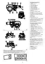
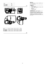
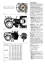
KESSELPLATTE (A)
Die Abdeckplatte der Brennkammer wie in (A)
gezeigt vorbohren. Die Position der Gewinde-
bohrungen kann mit dem zur Grundausstattung
gehörenden Wärmeschild ermittelt werden.
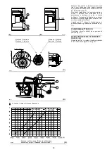
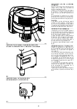
FLAMMROHRLÄNGE (B)
Die Länge des Flammrohrs wird entsprechend
der Angaben des Kesselherstellers gewählt und
muß in jedem Fall größer als die Stärke der Kes-
seltür einschließlich feuerfestes Material sein.
Für Heizkessel mit vorderem Abgasumlauf 1)
oder mit Flammenumkehrkammer muß eine
Schutzschicht aus feuerfestem Material 5),
zwischen feuerfestem Material des Kessels 2)
und Flammrohr 4) ausgeführt werden.
Diese Schutzschicht muß so angelegt sein, daß
das Flammrohr ausbaubar ist.
Für die Kessel mit wassergekühlter Frontseite
ist die Verkleidung mit feuerfestem Material 2)-
5)(B) nicht notwendig, sofern nicht ausdrücklich
vom Kesselhersteller erfordert.
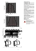
BEFESTIGUNG DES BRENNERS AM
HEIZKESSEL (B)
• Ein passendes Hebesystem vorbereiten und
an den Ringen 3)(B) einhängen.
• Den mitgelieferten Wärmeschutz am Flam-
mrohr 4)(B) einstecken.
• Wie in Abb. (A) gezeigt, den ganzen Brenner
in das vorher vorbereitete Loch am Heizkes-
sel einstecken und mit den mitgelieferten
Schrauben befestigen.
Die Dichtheit zwischen Brenner und Heizkes-
sel muss hermetisch sein.
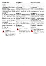
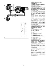
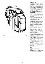
ZUGÄNGLICHKEIT ZUM INNENTEIL
DES FLAMMKOPFS (C)
• Die 4 Befestigungsschrauben 1) entfernen
und den Brenner am Scharnier öffnen – siehe
Abb. (C).
• Den Steckanschluss 6) abtrennen.
• Die Kabel der Elektroden 2) aushängen.
• Die Schraube 4), die den Kopf blockiert, loss-
chrauben.
• Die Heizölrohre abtrennen, indem die beiden
drehbaren Anschlüsse 3) losgeschraubt
werden.
Anmerkung: das mögliche Austreten einiger
Brennstofftropfen beim Losschrauben
beachten.
• Das Innenteil des Kopfes 5) herausnehmen.
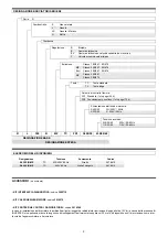
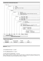
WAHL DER DÜSE FÜR DIE 1. UND 2. STUFE
Beide Düsen werden unter den in der Tabelle
(D) angegebenen Typen ausgewählt.
Die erste Düse bestimmt den Durchsatz des
Brenners in der 1. Stufe.
Die zweite Düse funktioniert zusammen mit der
ersten und beide bestimmen den Durchsatz des
Brenners in der 2. Stufe.
Die Durchsätze der 1. und 2. Stufe müssen
innerhalb der auf Seite 4 angegebenen Werte
sein.
Düsen mit einem Zerstäubungswinkel von 60° beim
empfohlenen Druck von 12 bar verwenden.
Die beiden Düsen haben im allgemeinen gleiche
Durchsätze, die Düse der 1. Stufe kann jedoch
einen Durchsatz von weniger als 50% des Ges-
amtdurchsatzes haben, wenn der Spitzenwert
des Gegendrucks im Augenblick des Zündens
vermindert werden soll (der Brenner gestattet
gute Verbrennungswerte auch mit Verhältnissen
von 33 - 100 % - zwischen 1. und 2. Stufe).
Beispiel
Kesselleistung = 1630 kW - Wirkungsgrad 90 %
Geforderte Brennerleistung =
1630 : 0,9 = 1812 kW;
1812 : 2
= 906 kW pro Düse
erfordert werden 2 gleiche Düsen, 60°, 12 bar:
1° = 18 GPH - 2° = 18 GPH,
oder zwei unterschiedliche Düsen:
1° = 15 GPH - 2° = 21 GPH.
ANMERKUNG:
anstelle der in Tab. (D) angege-
benen Düsen können auch Düsen folgendes
Typs verwendet werden:
•
HAGO H
(bis zu 30 GPH) für
RL300
und den
Bereich A
des Diagramms (A) S. 16 decken.
•
DELEVAN B 60°
(oder 80° bis 50 GPH) für
RL400
und den Bereich
A
des Regelbere-
iches S. 16 decken.
•
MONARCH PL 70°
(bis 30 GPH) für
RL300
und den Bereich
A
des Regelbereiches S. 1 6
decken.
•
MONARCH PLP 70°
(bis 50 GPH) anstelle
der Düsen des Typs
HAGO S-S 60°
der
Tabelle (D).
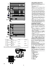
INSTALLATION
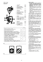
BOILER PLATE (A)
Drill the combustion chamber locking plate as
shown in (A). The position of the threaded holes
can be marked using the thermal screen sup-
plied with the burner.
BLAST TUBE LENGTH (B)
The length of the blast tube must be selected
according to the indications provided by the
manufacturer of the boiler, and in any case it
must be greater than the thickness of the boiler
door complete with its fettling.
For boilers with front flue passes 1) or flame
inversion chambers, protective fettling in refrac-
tory material 5) must be inserted between the
boiler fettling 2) and the blast tube 4).
This protective fettling must not compromise the
extraction of the blast tube.
For boilers having a water-cooled front the
refractory fettling 2)-5)(B) is not required unless
it is expressly requested by the boiler manufac-
turer.
SECURING THE BURNER TO THE
BOILER (B)
• Prepare an adequate system of hoisting by
hooking onto the rings 3)(B).
• Slip the thermal protection (standard equip-
ment) onto the blast tube 4) (B).
• Place entire burner on the boiler hole
(arranged previously, see fig. (A), and fasten
with the screws given as standard equipment.
The coupling of the burner-boiler must be air-
tight.
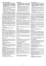
ACCESSIBILITY TO THE INTERIOR OF
THE COMBUSTION HEAD (C)
• Open burner at hinge (see fig. C) after remov-
ing the 4 fixing screws 1).
• Disconnect the plug 6)
• Disconnect the wires from the electrodes 2).
• Unscrew the screw 4) that fix combustion
head
• Disconnect the oil pipes by unscrewing the
two connectors 3).
Note: While unscrewing, some fuel may leak
out.
• Extract the internal part 5) of the combustion
head.
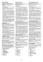
CHOICE OF NOZZLES FOR 1ST AND 2ND
STAGE
Both nozzles must be chosen from among those
listed in Table (D).
The first nozzle determines the delivery of the
burner in the 1st stage.
The second nozzle works together with the 1st
nozzle to determine the delivery of the burner in
the 2nd stage.
The deliveries of the 1st and 2nd stages must
be contained within the value range indicated on
page 8.
Use nozzles with a 60° spray angle at the rec-
ommended pressure of 12 bar.
As a rule the two nozzles have equal deliveries
but the 1st stage nozzle may have a delivery
less than 50% of the total delivery when a
reduction of the counter-pressure peak is
desired at the moment of starting (the burner
allows good combustion rates also with a 33 -
100 % ratio between the 1st and 2nd stage).
Example
Boiler output = 1630 kW - efficiency 90 %
Output required by the burner =
1630 : 0,9 =1812 kW;
1812 : 2
=906 KW per nozzle;
therefore, two equal, 60°, 12 bar nozzles are
required:
1° = 18 GPH - 2° = 18 GPH,
or the following two different nozzles:
1° = 15 GPH - 2° = 21 GPH.
NOTE:
Instead of the nozzles given in tab. (D),
you can use the following nozzle types:
•
HAGO H
(up to 30 GPH) for
RL300
and cover
area A
in diagram (A)
on page 16.
•
DELEVAN B 60°
(or 80° up to 50 GPH) for
RL400
and cover area
A
in firing rate
on page
16.
•
MONARCH PL 70°
(up to 30 GPH) for
RL300
and cover area
A
in firing rate
on page 16.
•
MONARCH PLP 70°
(up to 50 GPH) as noz-
zles to be used instead of type
HAGO S-S
60°
given in table (D).
INSTALLATION
PLAQUE CHAUDIERE (A)
Percer la plaque de fermeture de la chambre de
combustion comme sur la fig.(A). La position
des trous filetés peut être tracée en utilisant
l'écran thermique fourni avec le brûleur.
LONGUEUR BUSE (B)
La longueur de la buse doit être choisie selon
les indications du constructeur de la chaudière,
en tous cas, elle doit être supérieure à l'épais-
seur de la porte de la chaudiäre, matériau
réfractaire compris.
Pour les chaudières avec circulation des
fumées sur l'avant 1), ou avec chambre à inver-
sion de flamme, réaliser une protection en
matériau réfractaire 5), entre réfractaire chau-
dière 2) et buse 4).
La protection doit permettre l'extraction de la
buse.
Pour les chaudières dont la partie frontale est
refroidie par eau, le revêtement réfractaire 2)-
5)(B) n'est pas nécessaire, sauf indication pré-
cise du constructeur de la chaudière.
FIXATION DU BRULEUR A LA CHAUD-
IERE (B)
• Prévoir un système de soulèvement appro-
prié et l’accrocher aux anneaux 3)(B).
• Enfiler la protection thermique de série sur la
buse 4)(B).
• Enfiler entièrement le brûleur sur le trou de la
chaudière prévu précédemment, comme
indiqué sur la fig. (A) et fixer avec les vis
fournies de série.
Le groupe brûleur-chaudière doit avoir une
étanchéité parfaite.
POSSIBILITÉ D’ACCÉDER À LA PARTIE
INTERNE DE LA TÊTE DE COMBUS-
TION (C)
• Ouvrir le brûleur sur la charnière comme
indiqué sur la fig. (C) après avoir enlevé les 4
vis de fixation 1).
• Débrancher la prise 6).
• Détacher les câbles des électrodes 2).
• Dévisser la vis 4) qui bloque la tête.
• Détacher les tuyaux du fioul en dévissant les
deux raccords 3).
Remarque: faire attention car quelques
gouttes de combustible peuvent couler au
moment de dévisser les pièces.
• Extraire la partie interne de la tête 5).
CHOIX DES GICLEURS POUR LA 1ère ET LA
2ème ALLURE
Les deux gicleurs doivent être choisis parmi
ceux indiqués dans le tableau (D).
Le premier gicleur détermine le débit du brûleur
à la 1ère allure.
Le deuxième gicleur fonctionne en même temps
que le premier et tous les deux déterminent le
débit du brûleur à la 2ème allure.
Les débits de la 1ère et de la 2ème allure doivent être
compris dans les limites indiquées à la page. 10.
Utiliser des gicleurs à angle de pulvérisation de
60° à la pression conseillée de 12 bar.
Généralement, les deux gicleurs ont le même
débit mais, en cas de besoin, le gicleur de la
1ère allure peut avoir un débit inférieur à 50%
du débit total, quand on veut réduire la pointe de
contre-pression au moment de l'allumage (le
brûleur permet d’avoir de bonnes valeurs de
combustion même avec un rapport 33 - 100 %
entre la 1ère et la 2ème allure).
Exemple
Puissance chaudière = 1630 kW
rendement 90 %
Puissance requise au brûleur =
1630 : 0,9 = 1812 kW;
1812 : 2
= 906 kW par gicleur
Il faut 2 gicleurs identiques, 60°, 12 bar:
1ère = 18 GPH - 2eme = 18 GPH,
ou bien deux gicleurs différents:
1ère = 15 GPH - 2ème = 21 GPH.
NOTE:
Il est possible d’utiliser les gicleurs suiv-
ants à la place de ceux indiqués dans le tableau
(
D
):
•
HAGO H
(jusqu’à 30 GPH) pour
RL300
et cou-
vrir la zone A du diagramme A) de la page 16.
•
DELEVAN B 60°
(ou 80° jusqu’à 50 GPH)
pour
RL400
et couvrir la zone
A
de la plage
de travail de la page 16.
•
MONARCH PL 0°
(jusqu’à 30 GPH) pour
RL300
et couvrir la zone
A
de la plage de tra-
vail de la page 16.
•
MONARCH PLP 0°
(jusqu’à 50 GPH) comme
gicleurs pouvant remplacer le modèle
HAGO
S.S 60°
du tableau (D).
Summary of Contents for 966 T
Page 45: ...45 RL 300 B MZ...
Page 46: ...46 RL 400 B MZ...
Page 47: ...47...
Page 48: ...48 RL 300 B MZ...
Page 49: ...49 0 1 1 1 2 3 2 RL 400 B MZ...
Page 50: ...50 01123 0 3 112 01453 6 7 0 3 8 9 0 3 112 01453 6 7 8 9 8 8 9 8 9 76 76 A...
Page 53: ......
Page 54: ......
Page 55: ......


