
24
INNESCO POMPA
-
Accertarsi, prima di mettere in funzione il
bruciatore, che il tubo di ritorno in cis-
terna non abbia occlusioni. Un eventuale
impedimento provocherebbe la rottura
dell'organo di tenuta posto sull'albero
della pompa.
-
Perchè la pompa possa autoinnescarsi è
indispensabile allentare la vite 4) della
pompa per sfiatare l'aria contenuta nel tubo
di aspirazione.
-
Avviare il bruciatore chiudendo i teleco-
mandi. Appena il bruciatore si avvia control-
lare il senso di rotazione della girante del
ventilatore.
-
Quando il gasolio fuoriesce dalla vite 4) la
pompa è innescata. Fermare il bruciatore ed
avvitare la vite 4).
Il tempo necessario per questa operazione
dipende dal diametro e dalla lunghezza della
tubazione aspirante. Se la pompa non si
innesca al primo avviamento e il bruciatore va in
blocco, attendere circa 15 s, sbloccare e rip-
etere l'avviamento. E così di seguito. Ogni 5-6
avviamenti, attendere per 2-3 minuti il raffredda-
mento del trasformatore.
Non illuminare la cellula UV per evitare il blocco
del bruciatore; il bruciatore bloccherà in ogni
caso dopo una decina di secondi dal suo avvia-
mento.
Attenzione:
l'operazione suindicata è possibile
perchè la pompa lascia la fabbrica piena di com-
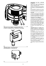
bustibile. Se la pompa è stata svuotata, riem-
pirla di combustibile dal tappo del vacuometro
4)(B) prima di avviarla, altrimenti grippa.
Quando la lunghezza della tubazione aspirante
supera i 20-30 m, riempire il condotto con
pompa separata.
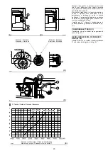
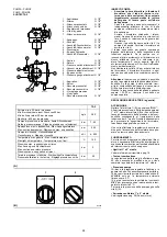
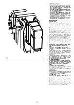
REGOLAZIONE BRUCIATORE (a gasolio)
ACCENSIONE
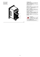
Mettere l'interruttore 1)(B) in posizione "MAN".
Alla prima accensione, all'atto del passaggio dal
1° al 2° stadio,interruttore 2(B) si ha un momen-
taneo abbassamento della pressione del com-
bustibile conseguente al riempimento della
tubazione del 2° ugello. Questo abbassamento
può provocare lo spegnimento del bruciatore,
talvolta accompagnato da pulsazioni.
Una volta effettuate le regolazioni descritte qui
di seguito, l'accensione del bruciatore deve gen-
erare un rumore pari al funzionamento.
FUNZIONAMENTO
Per ottenere una regolazione ottimale del bruci-
atore è necessario effettuare l'analisi dei gas di
scarico della combustione all'uscita della caldaia
ed intervenire sui punti che seguono.
• Ugelli di 1° e 2° stadio
Vedere informazioni riportate a pag. 18.
• Testa di combustione
La regolazione della testa già effettuata a pag.
20 non necessita di modifiche se non viene
cambiata la portata del bruciatore in 2° stadio.
• Pressione pompa
12 bar: è la pressione regolata in fabbrica e in
genere va bene. Può essere necessario portarla a:
10 bar per ridurre la portata del combustibile. E'
possibile solo se la temperatura ambiente
rimane sopra 0 °C;
14 bar per aumentare la portata del combusti-
bile o per avere accensioni sicure anche a tem-
perature inferiori a 0 °C.
Per variare la pressione della pompa agire sulla
vite 5)(A).
• Serranda ventilatore 1° e 2° stadio
Vedi regolazione pag. 28 (Servomotore).
(B)
D3359
(A)
D3255
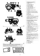
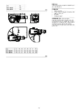
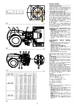
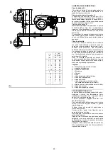
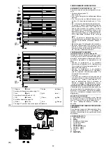
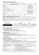
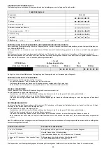
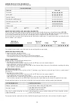
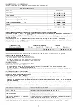
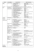
POMPA - PUMPE
PUMP - POMPE
SUNTEC TA 2
1 - Aspirazione
G 1/2"
2 - Ritorno
G 1/2"
3 - Attacco pressostato
G 1/8"
4 - Attacco vacuometro
G 1/8"
5 - Regolatore di pressione
6 - Vite di by-pass
7 - Attacco manometro
G 1/4"
1 - Ansaugen
G 1/2"
2 - Rücklauf
G 1/2"
3 - Anschluß Druckwächter
G 1/8"
4 - Anschluß Vakuummeter
G 1/8"
5 - Druckregler
6 - By-pass Schraube
7 - Anschluß Manometer
G 1/4"
1 - Suction
G 1/2"
2 - Return
G 1/2"
3 - Pressure switch attachment G 1/8"
4 - Vacuum meter attachment G 1/8"
5 - Pressure adjustment screw
6 - By-pass screw
7 - Pressure gauge attachment G 1/4"
1 - Aspiration
G 1/2"
2 - Retour
G 1/2"
3 - Raccord pressostat
G 1/8"
4 - Raccord vacuomètre
G 1/8"
5 - Vis réglage pression
6 - Vis by-pass
7 - Raccord manomètre
G 1/4"
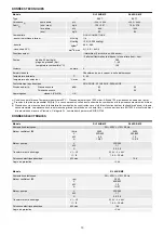
TA 2
Portata min. a 20 bar di pressione
Min.-Durchsatz bei einem Druck von 20 bar
Min. delivery rate at 20 bar pressure
Débit min. à 20 bar de pression
kg/h
380
Campo di pressione in mandata - Auslaß-Druckbereich
Delivery pressure range - Plage de pression en refoulement
bar
7 - 40
Depressione max in aspirazione - Max.-Ansaugunterdruck
Max. suction depression - Dépression max. en aspiration
bar
0,45
Campo di viscosità - Viskositätsbereich
Viscosity range - Plage de viscosité
cSt
4 - 800
Temperatura max. gasolio - Max. Heizöltemperatur
Max light oil temperature - Température max. fioul
°C
140
Pressione max. in aspirazione e ritorno
Max. Ansaug- und Rücklaufdruck
Max. suction and return pressure
Pression max. en aspiration et retour
bar
5
Taratura pressione in fabbrica - Werkseitige Druckeinstellung
Pressure calibration in the factory - Réglage pression en usine
bar
30
1
2
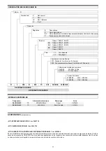
Summary of Contents for 966 T
Page 45: ...45 RL 300 B MZ...
Page 46: ...46 RL 400 B MZ...
Page 47: ...47...
Page 48: ...48 RL 300 B MZ...
Page 49: ...49 0 1 1 1 2 3 2 RL 400 B MZ...
Page 50: ...50 01123 0 3 112 01453 6 7 0 3 8 9 0 3 112 01453 6 7 8 9 8 8 9 8 9 76 76 A...
Page 53: ......
Page 54: ......
Page 55: ......


