background image

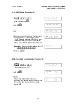
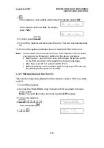
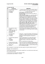
4.1.7. RAM Dump (Function 06)

 1. 

FU


6


1


9


9


5


then immediately 

Y


FUNCTION    KPAD/NEXT

 SERVICE FUNCTIONS

 2. 

0


6


Y


0-MEM.R/W 1-MEM.DUMP


 3. 

1


MEMORY DUMP  START/N

ADD.000000 - 0000FF

 
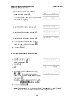
  4. Enter the first four digits of the start and

end addresses . For example, enter
“8000” for start address 800000(H), and
enter 8001 for end address 8001FF(H).
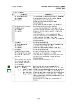
Then, press "Start" to print the dump list.

MEMORY DUMP

START/N

ADD. 800000- 8001FF

 Example: Start at 800000, end at 8001FF.


 80008001

S

 .

MEMORY DUMP


 5. Finish:  

FU

4.1.8.

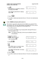
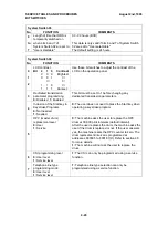
4.1.8. Counter Display/Rewrite (Function 07)

 1. 

FU


6


1


9


9


5


 then immediately 

Y


FUNCTION    KPAD/NEXT

   SERVICE FUNCTIONS

 2. 

0


7


Y


0-COUNTER     1-PM

2-CTM              3-OPU

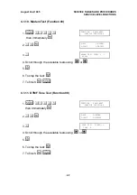
 3. Either:
   Check the transmitted, received,

scanned and printed page counters, and
the printer and scanner jam counters -

press 

0


TX:

012345

RX:

012345

August 2nd, 1995

SERVICE TABLES AND PROCEDURES

SERVICE LEVEL FUNCTIONS

4-5

Summary of Contents for FAX3700l

Page 1: ...FAX3700L SERVICE MANUAL September 21st 1995 Subject to change ...

Page 2: ... ALONG THE LASER BEAM PATH WHILE THE MAIN POWER IS ON Lithium Batteries Memory Back up ICAUTION The danger of explosion exists if a battery of this type is incorrectly replaced Replace only with the same or an equivalent type recommended by the manufacturer Discard used batteries in accordance with the manufacturer s instructions ...

Page 3: ... 1 17 1 5 3 Copying 1 18 1 5 4 Printing from the Optional Printer Interface 1 19 1 6 POWER DISTRIBUTION 1 20 1 6 1 Distribution Diagram 1 20 1 6 2 Memory Back up Circuit 1 21 2 DETAILED SECTION DESCRIPTIONS 2 1 SCANNER 2 1 2 1 1 Mechanisms 2 1 1 Document Detection 2 1 2 Pick up and Separation 2 1 3 Drive Mechanism 2 2 4 Image Scanning 2 3 5 Sub Scan Resolution Conversion 2 4 6 Stamping 2 4 2 1 2 S...

Page 4: ...2 11 Fusing 2 39 2 2 12 Page Separation and Data Reduction 2 43 2 2 13 Paper Size Selection 2 45 2 3 SYSTEM FEATURES 2 46 2 3 1 Power Saver Modes 2 46 1 Going into a Power Saver Mode 2 47 2 Going into Level 2 Mode from Level 1 Mode 2 49 3 Receiving a Fax Message in Power Saver Mode 2 51 4 Sending a Fax Message or Copying in Power Saver Mode 2 53 2 3 2 Automatic Service Calls 2 55 1 Service Call Co...

Page 5: ...face 3 4 4 SERVICE TABLES AND PROCEDURES 4 1 SERVICE LEVEL FUNCTIONS 4 1 4 1 1 Bit Switch Programming Function 01 4 1 4 1 2 System Parameter List Function 02 4 2 4 1 3 Error Code Display Function 03 4 3 4 1 4 Service Monitor Report Function 04 4 3 4 1 5 Protocol Dump Function 05 4 4 4 1 6 RAM Display Rewrite Function 06 4 4 4 1 7 RAM Dump Function 06 4 5 4 1 8 Counter Display Rewrite Function 07 4...

Page 6: ...ters 4 71 4 5 SERVICE RAM ADDRESSES 4 73 4 6 SPECIAL TOOLS AND LUBRICANTS 4 86 4 7 PM TABLE 4 86 5 REPLACEMENT AND ADJUSTMENT 5 1 COVERS 5 1 5 1 1 Document Table and Tray 5 1 5 1 2 Rear Cover Assembly 5 2 5 1 3 Left Cover 5 2 5 1 4 Right Cover 5 3 5 1 5 Operation Panel Assembly 5 3 5 1 6 Operation Panel and ADF Upper Unit 5 4 5 1 7 Top Cover 5 4 5 2 OPERATION PANEL 5 5 5 2 1 Operation Panel and OP...

Page 7: ...25 5 8 4 Registration Roller and Bypass Feed Sensor 5 26 5 9 PCBs 5 27 5 9 1 PSU and NCU 5 27 5 9 2 NCU FDU and FCE 5 27 5 9 3 Power Pack 5 28 5 10 OTHERS 5 29 5 10 1 Ozone Filter and Fan Motor 5 29 5 11 100 SHEET PAPER CASSETTE OPTIONAL 5 29 5 11 1 Relay Connector and Gear Cover 5 29 5 11 2 Paper End Sensor and Drive Components 5 30 5 11 3 Paper Size Sensor 5 31 5 12 IMAGE ADJUSTMENT 5 32 5 12 1 ...

Page 8: ...er 6 16 6 1 16 Misaligned Output Data shifted to the right or left 6 17 6 1 17 Misaligned Output Image shifted vertically Reduced Image 6 17 6 2 MECHANICAL PROBLEMS 6 18 6 2 1 ADF Scanner 6 18 1 Non Feed 6 18 2 Jam 6 19 3 Skew 6 20 4 Multi feed 6 20 6 2 2 Printer 6 21 1 Non feed 6 21 2 Paper Jam Inside Printer 6 22 3 Jam Fusing Exit 6 23 4 Skew 6 24 5 Multi feed 6 25 6 3 SERVICE CALL CONDITIONS 6 ...

Page 9: ... Group 3 with ECM Modulation V 33 V 17 TCM V 29 QAM V 27ter PHM V 21 FM Data Rate bps 14 400 12 000 9600 7200 4800 2400 Automatic fallback I O Rate With ECM 0 ms line Without ECM 2 5 5 10 20 or 40 ms line Transmission Time 6 s at 14 400 bps Measured with G3 ECM using memory for a ITU T 1 test document Slerexe letter at standard resolution Printing System Laser printing plain paper dry toner Paper ...

Page 10: ...dity 40 70 Rh Dimensions W x D x H 475 x 459 x 240 mm 18 7 x 18 1 x 9 4 ins Excluding handset trays and optional units Weight Approx 17 kg 37 lbs Excluding CTM handset trays and optional units OVERALL MACHINE INFORMATION August 2nd 1995 SPECIFICATIONS 1 2 ...

Page 11: ... ten numbers O Answering machine interface X Communication Features User Selectable Authorized Reception O Auto answer delay time X Auto dialing pulse or DTMF O Auto Document O Auto image density selection X Auto paper size selection X Automatic Voice Message X Batch Transmission max 6 files A Broadcasting O Chain Dialing O Communication Result Display X Confidential ID Override O Confidential Tra...

Page 12: ...ed mark O Clearing a memory file O Clearing a polling file O Clock O Confidential ID A Other User Features Copy editing Erase Center Mar gin X Copy mode O Copy Mode Restriction X Counters O Daylight Saving Time O Destination Check X Direct entry of names O File Retention Time X File Retransmission X Function Programs O ID Code O Label Insertion From xxx O Language Selection O LCD contrast control ...

Page 13: ...omm parameter display O Counter check O Country code O DTMF tone test O Echo countermeasure O Effective term of service calls O Error code display O Excessive jam alarm O Service Mode Features File Transfer O LCD contrast adjustment O Line error mark O Memory file printout all files O Modem test O NCU parameters O Operation panel test O Periodic service call O PM Call O Printer mechanism test O Pr...

Page 14: ...ocument from the document table one at a time 6 Pressure Plate This applies pressure against the pick up roller 7 CTM Cleaning Toner Magazine This consists of the toner cartridge cleaning unit used toner tank charge corona unit and quenching lamp 8 Used Toner Tank This removes and stores excess toner from the master after image transfer It is part of the CTM 17 18 19 20 21 23 22 24 27 26 30 28 25 ...

Page 15: ...s a charge to the paper to pull the toner off the drum and onto the copy paper 21 Development Roller This roller applies toner to the latent image on the drum 22 Toner Application Roller This roller transfers toner to the development roller 23 Toner Supply Bar This stirs up and transfers toner to the toner application roller 24 Paper Feed Rollers 100 Sheet Cassette These pick up the top sheet of p...

Page 16: ...ar This drives the pick up roller 6 Drum Drive Gear This drives the drum 7 Used Toner Collection Roller Drive Gear This drives the used toner collection roller magnetic in the used toner tank 8 Transfer Roller Drive Gear This drives the transfer roller 9 Hot Roller Drive Gear This drives the hot roller 10 Fusing Pressure Roller Drive Gear This drives the pressure roller in the fusing unit 1 2 3 5 ...

Page 17: ...epper motor drives the paper feed mechanisms and the registration roller 17 Paper Feed Roller Drive Gear Box The gears in this box drive the paper feed roller in the main cassette 18 Paper Feed Roller Drive Gear This drives the paper feed roller 19 Main Motor This brushless dc motor drives the drum fusing unit development unit and CTM 20 Toner Supply Gear This ensures the supply of toner from the ...

Page 18: ...1 3 3 Electrical Components 5 3 7 4 6 2 8 9 10 11 14 13 12 1 H516V503 wmf OVERALL MACHINE INFORMATION August 2nd 1995 COMPONENT LAYOUT 1 10 ...

Page 19: ...re transfer roller and development rollers 4 Contact Image Sensor Assembly This sensor reads and converts the light reflected from the document into an analog video signal It uses an RLA Rod Lens Array sensor unit An LED array which illuminates the document is contained in this unit 2 Motors No Name Description 14 Tx Motor This stepper motor drives the scanner 13 Main Motor This brushless dc motor...

Page 20: ...the cassette has run out 26 Registration Sensor This detects when paper has reached the registration roller 29 Fusing Exit Sensor This detects when the paper has been fed out of the printer 28 Fusing Exit Cover Switch This detects whether the fusing exit cover is open or closed 25 Bypass Feed Sensor This detects when a sheet of paper has been inserted into the bypass feed slot Then the registratio...

Page 21: ...ge Corona Unit This applies a charge to the drum at the start of the print cycle This is a part of CTM 23 Thermostat This interrupts the ac power supply to the fusing lamp if the temperature of the thermostat surface exceeds 400 C 24 Thermistor This monitors the temperature at the hot roller surface 22 Fusing Lamp The heat from this lamp fuses the toner to the paper 18 Monitor Speaker This allows ...

Page 22: ...te This increases the paper capacity of the machine and allows the machine to have more than one paper size available at the same time 39 Paper Size Detector 100 Sheet Cassette This detects the paper size installed in the cassette 40 Paper End Sensor 100 Sheet Cassette This detects when the paper in the cassette has run out 41 Paper Feed Clutch 100 Sheet Cassette This transfers drive from the pape...

Page 23: ...ed for V 17 and V 33 communications The 1 5 MB DRAM contains the SAF memory ECM buffer memory work area and page memory The SAF memory can be extended by 2 or 4 Mbytes with an IC card A 512 kB 4 Mbit flash ROM is used for the system ROM Software in this ROM can be rewritten from the IC card slot or by RDS Another 128 kB mask ROM contains LCD wording data Contact Image Sensor Amplifier Optional 100...

Page 24: ...e for transmission the DCR block decompresses the data from the SAF memory then compresses it again after handshaking with the other ter minal is done The compressed data then passes either to the FIFO memory or to the ECM memory before it is sent to the telephone line through the modem FDU FCE DRAM Video Processing Memory Line Buffer FIFO Memory ECM SAF Memory Amplifier MDM FCIP DATA ADDRESS BUS ...

Page 25: ...case of mechanical problems dur ing printing substitute reception The raster image data is then passed to the page memory for printing After a page of data has been stored in the page memory the data is sent to the LDDR through the LIF block Copy Paper DATA ADDRESS BUS E144EFXL Modem Amplifier FCIP MDM DCR LIF HIC NCU From the Network Line Buffer FIFO Memory ECM SAF Memory Page Memory DRAM LDDR LI...

Page 26: ...of data has been stored in the SAF memory the data passes to the DCR block again for decompression then it passes to the page memory for printing FDU FCE LIF SAF Memory IC Card DIP DCR FCIP Video Processing Memory LDDR Amplifier Original DATA ADDRESS BUS Copy Paper Image Sensor Contact Image Sensor Assembly LED Array DRAM Line Buffer FIFO Memory ECM SAF Memory Page Memory LIF Laser Interface DCR D...

Page 27: ...fter a page of data has been stored in the printer interface s page memory the data is sent to the LIF through the PRIF Printer Interface block FDU FCE LIF FCIP LDDR Copy Paper PRIF Optional Printer Interface LIF Laser Interface PRIF Printer Interface H516V510 wmf August 2nd 1995 OVERALL MACHINE INFORMATION VIDEO DATA PATH 1 19 ...

Page 28: ...on when the main switch is on 24VD This is interrupted if the fusing unit cover interlock switch opens 24VIN This supplies 24V to the fusing unit on off switching circuit It is interrupted if the fusing unit cover interlock switch opens 24VM This is interrupted if the machine enters energy saving mode 5V This is used for the image sensor 12VP This is supplied to the Flash ROMs on the FCE and the o...

Page 29: ...ory and the power is switched off While the main power is on the 5VE supply recharges the battery The battery recharges in one or two days The battery B generates about 3 volts max 3 2 volts The dc dc converter IC12 lifts this voltage to 5 volts so it can be used as the 5VD supply for SAF backup The CPU monitors the voltage of the 5VD supply with the 1VDET signal When the battery has run down and ...

Page 30: ...achine starts feeding the document the mechanical clutch mechanism in the ADF roller unit lifts up the pick up roller B to feed the bottom sheet of the document Then the feed roller C feeds the sheet into the scanner The separation rubber plate D prevents the feed roller from feeding more than one sheet at a time Cross reference ADF mechanical clutch mechanism Group 3 Facsimile Manual page 2 2 8 B...

Page 31: ...andard Immediate Tx or Single copy mode 5 65 s Detail 5 65 s Fine 11 30 s The scanner can feed paper up to 304 mm 12 0 wide However the ac tual scan width is 256 mm 10 1 The maximum acceptable document page length can be adjusted to 0 6 m 23 6 1 2 m 47 2 or 14 m 46 ft The default setting is 1 2 m Cross reference Maximum document length Scanner Switch 00 bits 2 and 3 D B A C E H516D502 wmf DETAILED...

Page 32: ... than for a CCD type scanner Because of this the spring G pushes the shading plate A so that the document surface always touches the exposure glass at the scan line The image sensor assembly is adjusted at the factory so it does not need any adjustment at replacement in the field The image sensor scans the original one line at a time and outputs an ana log signal for each line The voltage from eac...

Page 33: ...ersion Fine The machine feeds and scans the document in 15 4 line mm steps The scanned lines are transmitted without any conversion In memory trans mission if the other terminal cannot receive a message at Fine resolution alternate lines even numbered lines are deleted before transmission 6 Stamping The original always stops at the stamping position after the page was trans mitted immediate transm...

Page 34: ...ng Chart 1 Timing Chart The following describes what is happening at points 1 to 6 on the timing chart T1 3 7 s T2 T3 Max 11s 23s or 46s 1 2 3 4 5 6 H516D543 wmf August 2nd 1995 DETAILED SECTION DESCRIPTIONS SCANNER 2 5 ...

Page 35: ...ncorrect sensor conditions The scan line sensor switches on while the document sensor is off T2 Maximum document length exceeded The scan line sensor does not turn off after the maximum document length has been fed since it turned on T3 This is after 11 s at standard resolution for memory tx 23 s at standard resolution for immediate tx or at detail resolution or 46 s at fine resolution all these t...

Page 36: ...or assembly is amplified on the FDU then transferred to the DIP Digital Image Processor inside the FCIP FDU FCE FCIP DIP Original Image Sensor LED Array Amplifier Analog data Video SRAM VRAM Binary data Contact Image Sensor Assembly H516D545 wmf August 2nd 1995 DETAILED SECTION DESCRIPTIONS SCANNER 2 7 ...

Page 37: ...Analog Digital AAAA AAAA AAAA AAAA AAAA AAAA AAAA AAAA AAAA AAAA AAA AAA AAA AAA AAA Standard resolution 15 4 l mm 15 4 l mm 15 4 l mm 15 4 l mm 3 85 l mm 1st Line 2nd Line 3rd Line 4th Line AAAA AAAA AAAA AAAA AAAA AAAA AAAA AAAA AAAA AAAA AA AA AA AA AA Detail resolution 1st Line 2nd Line 3rd Line 4th Line 7 7 l mm 7 7 l mm 15 4 l mm 15 4 l mm 15 4 l mm 15 4 l mm HALFTONE RESOLUTION CONVERSION H...

Page 38: ... the VOFFCNT signal in the above diagram if the peak voltage of the analog video signal B exceeds 234 mV in this condition Then the machine adjusts the signal s amplification ratio by switching the VGCOM signal if the peak output level of the analog video signal while the scanner lamp is on is lower than 1 72V The machine will execute the above adjustments automatically just be fore scanning the f...

Page 39: ...rast selected by the user 4 Erasure of irregular dots If an element after being converted to white or black by the above thre sholding is irregular against the surrounded pixels it is output in the op posite color The central pixel is compared with the surrounding eight pixels to determine whether this process is necessary There are ten cases as shown below in which conversion is done This results...

Page 40: ...rmine whether it is on a edge of a image pattern 3 Halftone process Each pixel is converted to six bit 0 63 using either the dither or the er ror diffusion formula At the same time if the pixel is on a edge of a im age pattern it is enhanced to to get a sharp outline Then each pixel is thresholded with the corresponding threshold in a dither matrix or error diffusion matrix 3 Video Processing Para...

Page 41: ...he bias voltages during printing are as follows Toner application roller 700 V Development roller 400 V The transfer roller pulls the toner from the drum onto the paper A constant current of 4 µA is applied The antistatic brush helps to separate the paper from the drum The cleaning blade removes any toner remaining on the drum after the image is transferred to the paper The quenching lamp reduces ...

Page 42: ...power pack B applies a constant current of 305 5 µA the voltage is about 5 3 kV The grid plate C ensures that the charge is uniformly spread out The zener diode D ensures that the charge on the drum does not exceed 750 50 V The charge corona unit contains a wire cleaner E for user maintenanace The ozone fan on the left hand side of the machine provides air flow to the charge corona unit and the oz...

Page 43: ...er by lighting the Call Service indicator error code 9 17 Charge Control In this machine a higher corona wire current is used to counter black bands on copies The charge on the drum exceeds the zener diode voltage because of this higher current Power Pack Driver EXIO CPU 1 43 21 1 Power Pack 21 3 21 8 698 V 24VM Leak Signal Charge Fusing Unit Cover Interlock Switch ON OFF IC8 IC4 FCE FDU H516D557 ...

Page 44: ... beam to the laser sychroni zation detector circuit in the FDU The shape of the mirror E is hexagonal The strength of the beam emitted from the LD unit F is 5 mW at a wavelength of 780 nm The dimensions of the dot on the drum are 85 µm by 85 µm The hexagonal mirror motor speed depends on the printing resolution Copy and G3 l mm mode 16 x 15 4 dots mm 10402 rpm Printer mode 300 dpi 7977 8 rpm The c...

Page 45: ...a mirror motor error when FDU CN14 4 does not go low within 10 seconds of the hexagonal mirror motor being turned on The machine also detects a mirror motor error when FDU CN14 4 goes back to high for 3 seconds or more during mirror motor operation When either of these errors occurs the machine warns the customer with the Call Service in dicator error code 9 23 FDU FCE LDDR FCIP Laser Synch Detect...

Page 46: ...ted not by varying the development bias In toner saving mode the im age data is filtered through the following four line matrix 1st line 1 0 1 0 1 0 1 0 1 0 2nd line 0 0 0 0 0 0 0 0 0 0 3rd line 0 1 0 1 0 1 0 1 0 1 4th line 0 0 0 0 0 0 0 0 0 0 1 Actual data printed black or white 0 Always a white pixel Note Toner saving mode only works when printing fax messages and re ports However toner saving i...

Page 47: ...supplied to the development unit from the outer openings D E in the CTM The spiral mechanism F on the toner supply bar distributes toner through the development unit Openings in the central area of the CTM G allow toner to circulate upwards from the development unit This circulation prevents excessive toner supply to the development unit and ensures that the toner remains fresh this helps to preve...

Page 48: ...s replaced Cross Reference Initial Toner Supply RAM address 8003C1 See sections 4 5 and 5 6 4 for more details CTM Detection At the following times the machine detects if a CTM is installed by checking the power supply to the quenching lamp this is part of the CTM At power up When the machine comes back to normal mode from the Level 2 Power Saver Mode When the cover is opened and then closed The m...

Page 49: ...ted the machine can print 100 more sheets then the cpu disables printing this is the toner end condition The machine clears the toner near end or toner end condition when the power is switched off and back on or when the cover is opened and closed if the output from the toner end sensor goes back high again However when the machine is turned off on or when the cover is opened and then closed the m...

Page 50: ... difference between these two rollers The exposed area on the drum E is at 100 V The development roller ap plies toner to these areas of the latent image as they turn past the drum The development roller is made of a soft rubber so it does not damage the surface of the drum The development roller is provided as a separate spare part because it always contacts the toner application roller and so ma...

Page 51: ...r application roller and 400 10 V is applied to the development roller Toner transfers from the toner applica tion roller to the development roller and on to the laser exposed areas on the drum as shown below D B C A H516D518 wmf E A H516D519 wmf Development Roller Toner Application Roller GND 750V 400V 700V 100V Print Data White Black Drum Surface Voltage Toner Drum Exposed Area H516D555 wmf DETA...

Page 52: ...ng toner on the develp ment roller does not transfer to the drum at B but transfers to the toner application roller at C In some cases positively charged toner may transfer to the drum in this condition So a positive current is applied to the transfer roller after each page so that the positively charged toner does not transfer to the transfer roller 750 V 400V GND 400V Drum Development Roller Ton...

Page 53: ... is to avoid any toner transfer to the drum Note that the voltage difference between the toner application and develop ment rollers is kept the same as in printing at 300 V This keeps the same amount of toner on the development roller at all times during the print run Development Roller Toner Application Roller GND 50V 250V Drum Surface Voltage Toner H516D550 wmf DETAILED SECTION DESCRIPTIONS Augu...

Page 54: ...w High Low High Bias 1 Low Low High High Out Toner Application Roller 700 V 50 V Off Off Development Roller 400 V 250 V 400 V Off FDU FCE CPU 1 44 1 45 1 83 1 87 Power Pack Driver Bias 0 Bias 1 Transfer 0 Transfer 1 Power Pack Toner Application Roller Development Roller Transfer Roller IC4 21 6 21 7 21 4 21 5 H516D552 wmf August 2nd 1995 DETAILED SECTION DESCRIPTIONS PRINTING 2 25 ...

Page 55: ... D rotates counter clockwise when the standard cas sette is used It rotates clockwise when the bypass feed slot B or the 100 sheet cassette is used When a sheet of paper is placed in the bypass feed slot the bypass feed sen sor E is turned on and the machine prefeeds the paper until the registration sensor F is turned on Note that the bypass feed slot can be used only for copying or for printing f...

Page 56: ...by the projection B and comes off the bottom hook C Once the slide lock comes off the bottom plate is raised by the pressure springs and the top sheet pushes up against the corner separators D This keeps the stack of paper at the correct height D D B H516D508 wmf C B A H516D509 wmf August 2nd 1995 DETAILED SECTION DESCRIPTIONS PRINTING 2 27 ...

Page 57: ... the bottom plate Selectable cassette paper sizes USA model Letter Legal when the optional Universal cassette is installed Europe model A4 A5 sideways Asia model A4 A5 sideways F F4 The following diagram shows the relationship between the activated mi croswitches and the selected paper size Microswitch USA Model Europe Model Asia Model 000 001 Legal 010 011 Letter 100 F F4 101 A4 A4 110 111 A5 sid...

Page 58: ...ork in the same way as in the standard cas sette When the 100 sheet cassette runs out of paper the paper end sensor actua tor B drops through a slot to detect paper end Paper Size Paper End Detection FDU FCE FCIP CPU Paper End Sensor Standard Cassette Paper Size Detector Standard Cassette Paper Size Detector 100 Sheet Cassette Paper End Sensor 100 Sheet Cassette EXIO 20 1 20 2 20 4 25 4 25 6 20 5 ...

Page 59: ...he paper feed motor A drives the pick up and feed mechanism When the standard cassette is used the paper feed motor turns clockwise driving the paper feed rollers B and the registration roller C as shown in the diagram The clutch gear box assembly D only allows the paper feed roller to turn once for each sheet of paper While the registration roller turns counter clockwise paper cannot be fed into ...

Page 60: ...rs for the standard cassette If a sheet of paper remains in the bypass feed slot for longer than the Auto Reset Time System Switch 0B the machine will automatically feed it out The machine will not print incoming fax messages while there is a sheet of pa per in the bypass feed slot so feeding out the page after the Auto Reset time allows incoming faxes to be printed even if someone leaves paper in...

Page 61: ...nd or paper feed unit installed in the ma chine the priority for paper feed is decided in accordance with the following rules The paper in the bypass feed slot has the first priority for copying and printing from a PC only If all the cassettes contain paper of the same size the machine uses the paper in the optional paper feed unit first the paper in the optional 100 sheet cassette second and the ...

Page 62: ...stration sensor is turned on When the bypass feed slot is used the machine prefeeds the paper until the registration sensor is turned on or for 1 second whichever comes first Then the paper feed motor starts rotating immediately after laser scaninng starts When the leading edge touches the pressure rollers the momentum of the paper corrects any skew A B H516D515 wmf August 2nd 1995 DETAILED SECTIO...

Page 63: ...s enabled 9 50 When the registration sensor in the fax machine is not turned on within 2 0 seconds after the paper feed motor started 9 51 When the bypass feed slot is used When the registration sensor is not turned on within 2 seconds after the paper feed motor starts rotating for printing This error is not generated during prefeed to allow the users to change their minds after putting paper in t...

Page 64: ... positively biased transfer roller pulls negatively charged toner off the drum The curvature of the drum and the antistatic brush helps the paper to drop away from the drum Temperature and humidity have less effect on the supply of ions when the transfer current is held constant With a constant voltage ions may dissipate in some conditions B A H516D520 wmf H516D553 wmf August 2nd 1995 DETAILED SEC...

Page 65: ...e machine goes through the cleaning mode in the following conditions At power on when the fusing temperature reaches half of the standby temperature When the cover is opened and then closed during the printing process After a printer jam has been cleared After the bypass feed slot has been used each page This is done only if printer switch 00 bit 3 is set to 1 The cpu controls the transfer roller ...

Page 66: ...nching lamp turn on T1 Cleaning bias is applied to the transfer roller T2 A positive constant current of 4 0 2 µA is applied to transfer back to the drum any toner which is positively charged by the transfer roller H516D563 wmf August 2nd 1995 DETAILED SECTION DESCRIPTIONS PRINTING 2 37 ...

Page 67: ...r tank D The mylar blade C scrapes the toner off the mag netic roller into the used toner tank D When the CTM is removed from the machine the cleaning roller cover E is closed by a spring This prevents removed toner from falling out of the unit There is no used toner overflow detection mechanism because the used toner tank is large enough for the lifetime of the CTM A B E D C H516D521 wmf DETAILED...

Page 68: ...oller would be about 400 C Thermofuse maximum 169 C the temperature of the hot roller would be about 400 C The thermofuse is not used in USA models AAAA AAAA AAAA AAAA AAAA AAAA AAAA AAAA AAAA AAAA AAAA AAAA AAAA AAAA AAAA AAAA AAAA AAAA AAAA AAAA AAAA AAAA AAAA AAAA AAAA AAAA AAAA AAAA AAAA AAAA AA AA AA AA AA AAAA AAAA AAAA AAAA AAAA AA AA AA AA AA AAAA AAAA AAAA AAAA AAAA AAAA AAAA AAAA AAAA AA...

Page 69: ... 22 sub code 09 is generated As a backup safety measure when the temperature of the hot roller reaches about 400 C the thermostat and or the thermofuse open the thermofuse is not installed in USA models The machine turns on the cooling fan when the fusing temperature reaches 120 C It is turned off when the fusing temperature drops below 120 C FDU FCE CPU 25 1 25 2 12 1 12 2 Comparator 5V 5V Intial...

Page 70: ... detects a paper jam when the paper feed out sensor is not turned off within X seconds or more after it is turned on Error Code 9 09 X seconds paper length 67 546 3 seconds 67 546 mm s is the paper feed speed These conditions are the same for the standard universal cassette bypass feed and optional 100 sheet cassette A B H516D522 wmf August 2nd 1995 DETAILED SECTION DESCRIPTIONS PRINTING 2 41 ...

Page 71: ...ng printing If the fusing temperature stays above 190 C for more than 60 seconds Sub code 01 If the fusing temperature stays below 140 C for more than 1 s during printing Sub code 07 After printing If the fusing temperature takes more than 20 minutes to go down to 100 C when the machine goes into the Power Saver Mode Level 1 When fusing lamp OFF is selected for Power Saver Mode Level 1 Sub code 03...

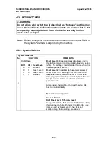
Page 72: ...programmed with a separate reduction ratio In each of the two bit switches there is one bit for each possible paper size The com bination of the bit settings determines the ratio for that paper size Bit No Switch No Bit 7 Bit 6 Bit 5 Bit 4 Bit 3 Bit 2 Bit 1 Bit 0 Not used Not used Legal F F4 A4 Letter Not used A5 sideways Sw 04 0 4 3 1 4 3 0 8 7 1 12 11 0 0 1 1 Sw 05 The following table shows the ...

Page 73: ...it is 1 the bottom few lines of the page will continue from where the first page left off Reduction Disabled If bit 0 of printer switch 03 is at 0 Disabled the data will not be reduced However if the incoming page is up to x mm longer than the copy paper the excess portion will not printed The value of x can be from 0 to 15 mm It is determined by the setting of bits 4 to 7 of printer switch 03 Hex...

Page 74: ...int ing the received fax message is selected in accordance with the follow ing table of priorities The table assumes that reduction is enabled and that the reduction ratio is 4 3 Received Fax Message Size Selected Paper Size A5 sideways Letter A4 F F4 Legal A5 Sideways 1 2 3 4 5 Letter 5 SR 1 2 3 4 A4 5 SR 4 R 1 2 3 F F4 5 SR 4 R 3 R 1 2 Legal 5 SR 4 R 3 R 2 R 1 The paper size priority is graded f...

Page 75: ...A AAAA AAAA AAAA AAAA AAAA AAAA AAAA AAAA AAAA AAAA AAAA AAAA AAAA AAAA AAAA AAAA AAAA AAAA AAAA AAAA AAAA AAAA AAAA AAAA AAAA AAAA AAAA AAAA AAAA AAAA AAAA AAAA AAAA AAAA AAAA AAAA AAAA AAAA AAAA AAAA AAAA AAAA AAAA AAAA AAAA AAAA AAAA AAAA AAAA AAAA AAAA AAAA AAAA AAAA AAAA AAAA AAAA AAAA AAAA AAAA AAAA AAAA AAAA AAAA AAAA AAAA AAAA AAAA AAAA AAAA AAAA AAAA AAAA AAAA AAAA AAAA AAAA AAAA AAAA AAA...

Page 76: ...r saver timer initial setting System Switch 0B bits 2 and 3 1 minute 3 minutes 5 minutes or Unlimited Timer disabled Power Saver Key When this key is pressed the machine checks if there are any background operations in progress these are the condition 2 operations on the flow chart If there are none the machine will automatically go into a Power Saver Mode See point 2 on the flow chart Which Power...

Page 77: ...nication Error NCU Off Hook Optional Equipment Installed Memory 100 Tx File Polling Rx File Exists Condition 3 all cleared Machine is in operation Machine is in a service call condition Machine is in a service mode operation T 1 3 or 5 minutes No Yes Unlimited Power Saver Key Yes No Key pressed Original detected Handset off hook If key was pressed in the above condition Power Saver Mode Level 1 LC...

Page 78: ...empty Mechanical error s NCU off hook Optional equipment installed a paper feed unit printer interface and or RS232C interface If there is a tx file in the memory The machine stays in Power Saver Mode Level 1 until it is time to send the message The machine then enters Level 0 while the message is sent See point 1 on the flow chart When the Power Saver timer expires When the power saver timer expi...

Page 79: ...le in memory No Power Saver Mode Level 2 LCD OFF LED OFF Fusing OFF Main CPU OFF Power Saver CPU ON Timer 0 Timer T System SW 0B Bit 2 3 T 1 3 or 5 minutes User SW 05 Bit 6 Fusing Lamp OFF Yes No Condition 1 No OR No Yes Mechanical Errors Original detected Communication Error NCU Off Hook Optional Equipment Installed Memory 100 Tx File Polling Rx File Exists 1 2 H516D527 wmf DETAILED SECTION DESCR...

Page 80: ...em components are active in the background for receiving a fax message See point 1 on the flow chart Printing If either of the following conditions is not met condition 1 on the flow chart the machine will print out the fax message then return to Power Saver Mode in the manner described in the previous two flow charts in this section Power Saver mode is activated during the Night Timer period The ...

Page 81: ... Power Saver CPU OFF Memory Reception Power Saving Mode Program No No Power Saver Mode Level 1 LCD OFF LED OFF Fusing User SW 05 Setting Main CPU ON Power Saver CPU OFF Power Saver Mode is enabled by User Function 62 and the machine is in a Night Timer period Yes Fusing Heat up Message Printout 1 2 H516D528 wmf DETAILED SECTION DESCRIPTIONS August 2nd 1995 SYSTEM FEATURES 2 52 ...

Page 82: ...evel 2 or the main CPU Level 1 monitors signals from the following con dition 1 on the flow chart Power saver key Document sensor Off hook detector on the NCU When a signal from one of these has been detected the CPU wakes up all the components and the machine enters normal operating mode even during the Night Timer period After operations have been finished the machine goes back to a power saver ...

Page 83: ...Phone communication Fax transmission Making copies etc Power Saving Mode Program Standby Mode Yes Yes Message received in memory Operation Finished No No Power Saver key pressed Document set in ADF NCU off hook Power Saver Mode Level 1 LCD OFF LED OFF Fusing User SW 05 Setting Main CPU ON Power Saver CPU OFF H516D529 wmf DETAILED SECTION DESCRIPTIONS August 2nd 1995 SYSTEM FEATURES 2 54 ...

Page 84: ... 9 20 21 Fusing lamp failure 9 22 01 to 09 Hexagonal mirror motor failure 9 23 31 or 32 Main motor failure 9 24 41 or 42 Excessive jams in the ADF scanner None None Excessive jams in the printer None None The PM counter has reached the threshold 60 000 prints None None The PM interval has expired None None Cross reference Service station number Service Function 13 Troubleshooting Chapter 6 August ...

Page 85: ... paper is fed without a jam occuring NO JAM1 and NO JAM2 are both incremented by 1 When NO JAM1 reaches DEC 16 by default NO JAM1 is set to zero and JAM is decremented by 1 When NO JAM2 reaches CLR 48 by default NO JAM2 and JAM are both reset to zero The CALL DEC and CLR thresholds can be adjusted for each type of jam by rewriting RAM data The addresses of these thresholds are given on the next pa...

Page 86: ... automat ically after the call Then the alarm is disabled until either bit 3 or bit 4 of address 80033D H is reset to zero 3 Periodic Service Call The periodic service call notifies the condition of the machine to the service station The call is made periodically at a time interval programmed in the fol lowing RAM addresses Parameters Address H Call interval 01 through 15 month s BCD 00 Periodic S...

Page 87: ...Service indicator does not light for a PM service call and the ma chine can be operated normally after it has made the service call 5 Effective Term of Service Calls If a time limit for the effectiveness of service calls is programmed the ma chine stops making automatic service calls after the time limit Program the time limit at the following addresses This function is disabled when all of these ...

Page 88: ...erial interface to the FDU DRAM backup control Ringing signal Tone detection Fusing lamp control 2 Modem Rockwell R144EFXL V 17 V 33 modem FCE DATA ADDRESS BUS Mask ROM 128kB DRAM 1 5MB Flash ROM 512kB Video SRAM 8kB 12VP 5V Battery 5V IC6 FCIP 32 768kHz 29 952MHz Parallel IO Memory Card Optional RS232C Interface Optional FDU Serial IO SRAM 32kB R144EFXL Modem 5VBAT H516D530 wmf August 2nd 1995 DE...

Page 89: ...U 5 SRAM 32 kB SRAM for system and user parameter storage Backed up by the battery on the FCE 6 Video SRAM 8 kB SRAM for video processing 7 Oscillators 29 952 MHz oscillator for system clock generation 32 768 MHz oscillator for the real time clock This is backed up by the battery on the FCE 38 00053 MHz oscillator for the R144EFXL modem 8 Jumpers Switches and Test Points Item Description SW1 Switc...

Page 90: ...onitor speaker driver 5 DC DC Converters 5V generation 12V generation FCE Power Saver CPU MFPD External IO HIC M M Paper Feed Motor TX Motor Control Serial I F Interlock Switch 24V Interlock Switch 5V DC DC Converter 24V 24VM ON OFF 24VD DC DC Converter 12VP 5VE 5V 5VV ON OFF TB1 5V Flash ROM Boot Block Overwrite ON OFF PSU Fusing Lamp 5V 5VLD AC Input Serial I F M TX DATA RX DATA TX RX DATA NCU C...

Page 91: ...tion signal CN40 4 COM1 ground TB1 Switches the power supply to the flash ROM boot block on the FCE 1 2 pins shorted 12V the boot block can be overwritten 2 3 pins shorted 5V the boot block cannot be overwritten Warning Do not change this jumper setting unless the boot block in the Flash ROM needs to be overwritten by Function 12 Refer to Chapter 4 1 20 for more details 2 4 3 PSU 24Vdc generation ...

Page 92: ...horted when the machine is connected to a dry line JP6 Ring Detect OHDISW TIP RING T1 R1 T1 R1 TRXD Current Sensor ExDI Hook1 Hook0 24 V OHDISW 24V Ext Tel DP Off Hook Detection Relay NCU JP5 JP6 ExRing H516D533 wmf August 2nd 1995 DETAILED SECTION DESCRIPTIONS PCBs 2 63 ...

Page 93: ... Ireland H L L S S S Finland L H L O O O Switzerland L H L O O O Other L H L S O O L Low H High S Short O Open TIP RING SHUNT GS T1 R1 TRXD JP24 TIP RING SHUNT GS T1 R1 OHDISW Hook0 RSEL DOSW CMLSW Hook1 ExRing CSEL0 CSEL1 Ring Detection Circuit Current Sensor Filter 16Hz CML Relay DO Sw GSSW OHDI Sw GS Sw CN5 Loop Closure Circuit CN7 H516D534 wmf DETAILED SECTION DESCRIPTIONS August 2nd 1995 PCBs...

Page 94: ...tion 01 PABX access code RAM address 8000BB Function 06 Machine s serial number Function 14 Service station s fax number Function 13 PM call System switch 01 bit 0 Function 01 Periodic service call RAM address 800256 Function 06 Items to Program User Administrator Level Function No Clock Function 91 Initial programming items IDs Function 61 On off switches Function 62 Display report language Funct...

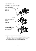
Page 95: ...print a setup sheet or a test pattern to check the controller Refer to the Operation Manual for the procedures Print a page from the PC to check the parallel interface A B H516I501 wmf A 2 screws B 1 screw C D H516I503 wmf Put back the rear cover first then install the brackets C and D C 2 screws D 2 screws F E H516I504 wmf Connect the harness E first then install the unit F F 2 hooks 3 screws INS...

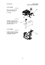
Page 96: ...A A 2 screws C H516I509 wmf Install the counter C in the rear cover connect it to the har ness from the FDU then put back the rear cover A H516I515 wmf Install the handset cradle A on the rear cover then connect the handset to the NCU April 5th 1996 INSTALLATION INSTALLING OPTIONAL UNITS 3 3 ...

Page 97: ...cover B from the rear cover A A 2 screws C D H516I506 wmf Attach the interface board C to the bracket D C 3 screws E H516I507 wmf Attach the interface board as sembly E to the machine con nect the harness to the FCE CN3 then put back the rear cover A E 2 screws INSTALLATION April 5th 1996 INSTALLING OPTIONAL UNITS 3 4 ...

Page 98: ...ONS 2 0 1 Y SYS DF 0000 0000 BITSW 00 0000 0000 Bit 7 is displayed at the left and bit 0 at the right 3 Scroll through the bit switch menu or Example To see the communication switches 3 Then scroll through the bit switches Increment bit switch Decrement bit switch Example Display bit switch 3 x 3 COM DF 0000 0000 BITSW 00 0000 0000 4 Adjust the bit switch Example To change the value of bit 7 press...

Page 99: ...re release date CONFIDENTIAL ID COUNTER NCU PARAMETER SERVICE NUMBER OWN NUMBER NUMBER MEMORY LOCK ID SWUSR User Parameter Settings SWITCH UPPER DEFAULT LOWER CURRENT PARAMETER TTI SCAN THRESHOLD 2MB or 4MB Optional memory card capacity installed CASSETTE 2 Optional paper feed unit installed SWSYS System Bit Switch Settings SWITCH UPPER DEFAULT LOWER CURRENT SWG3 G3 Bit Switch Settings SWCOM Commu...

Page 100: ...TIONS 2 0 3 Y ERROR CODE 1 01 JAN 01 17 30 3 Either Scroll through the error codes or Finish FU 4 1 4 Service Monitor Report Function 04 1 FU 6 1 9 9 5 then immediately Y FUNCTION KPAD NEXT SERVICE FUNCTIONS 2 0 4 Y S 3 Finish FU August 2nd 1995 SERVICE TABLES AND PROCEDURES SERVICE LEVEL FUNCTIONS 4 3 ...

Page 101: ...0 6 Y 0 MEM R W 1 MEM DUMP 3 0 ADDRESS 000000 DATA 00 4 Input the address that you wish to see Example Address 800020 8 0 0 0 2 0 ADDRESS 800020 DATA 20 Note If you wish to move the cursor press 5 If you wish to change the data type in the new data Example 80 press 8 0 ADDRESS 800020 DATA 80 Note If you wish to move the cursor press 6 Either View more addresses go to step 4 Finish FU SERVICE TABLE...

Page 102: ... Then press Start to print the dump list MEMORY DUMP START N ADD 800000 8001FF Example Start at 800000 end at 8001FF 80008001S MEMORY DUMP 5 Finish FU 4 1 8 4 1 8 Counter Display Rewrite Function 07 1 FU 6 1 9 9 5 then immediately Y FUNCTION KPAD NEXT SERVICE FUNCTIONS 2 0 7 Y 0 COUNTER 1 PM 2 CTM 3 OPU 3 Either Check the transmitted received scanned and printed page counters and the printer and s...

Page 103: ...en press Y 5 To finish FU 4 1 9 NCU Parameters Function 08 1 FU 6 1 9 9 5 then immediately Y FUNCTION KPAD NEXT SERVICE FUNCTIONS 2 0 8 Y 3 0 0 NCU 1 MODEM 2 DTMF 3 DETECT 4 Scroll through the parameters using or If you want to change a value enter the new value at the keypad then press Y Example Set NCU parameter 04 to 005 0 0 5 Y NCU KPAD NO 04 005 5 To finish N FU Note Parameter CC is the Count...

Page 104: ...able tests using or 5 S 6 To stop the test s 7 To finish N FU 4 1 11 DTMF Tone Test Function 08 1 FU 6 1 9 9 5 then immediately Y FUNCTION KPAD NEXT SERVICE FUNCTIONS 2 0 8 Y 0 NCU 1 MODEM 2 DTMF 3 DETECT 3 2 DTMF TEST START TONE 0 4 Scroll through the available tests using or 5 S 6 To stop the test s 7 To finish N FU August 2nd 1995 SERVICE TABLES AND PROCEDURES SERVICE LEVEL FUNCTIONS 4 7 ...

Page 105: ...SERVICE FUNCTIONS 2 0 8 Y 0 NCU 1 MODEM 2 DTMF 3 DETECT 3 3 MODEM DET START V21 300BPS 4 Scroll through the available tests using or 5 S 6 To stop the test s 7 To finish N FU 4 1 13 Ringer Test Function 08 1 FU 6 1 9 9 5 then immediately Y FUNCTION KPAD NEXT SERVICE FUNCTIONS 2 0 8 Y 0 NCU 1 MODEM 2 DTMF 3 DETECT 3 4 START RINGER 5 S 6 To stop s 7 To finish N FU SERVICE TABLES AND PROCEDURES Augus...

Page 106: ... LCD 3 0 4 S 5 To stop the test press s 6 To finish N FU 4 1 15 LED Array Test Function 10 1 FU 6 1 9 9 5 then immediately Y FUNCTION KPAD NEXT SERVICE FUNCTIONS 2 1 0 Y 0 LAMP 1 ADF 3 0 4 S START LAMP 0 0 0 5 To stop the test press s 6 To finish N FU August 2nd 1995 SERVICE TABLES AND PROCEDURES SERVICE LEVEL FUNCTIONS 4 9 ...

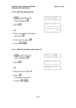
Page 107: ...hen press S 5 To stop the test press s 6 Finish N FU 4 1 17 Printer Test Patterns Function 11 1 FU 6 1 9 9 5 then immediately Y FUNCTION KPAD NEXT SERVICE FUNCTIONS 2 1 1 Y 0 PATTERN 1 MECH 3 0 PATTERN PRINT KPAD 0 4 5 Press a key from 0 to 4 6 Press S A test pattern is printed 7 To finish N FU SERVICE TABLES AND PROCEDURES August 2nd 1995 SERVICE LEVEL FUNCTIONS 4 10 ...

Page 108: ... FU 4 1 19 RAM Tests Function 12 1 FU 6 1 9 9 5 then immediately Y FUNCTION KPAD NEXT SERVICE FUNCTIONS 2 1 2 Y 0 SRAM 1 SAF 2 SAFCARD 3 M R 3 Either Test the SRAM Press 0 S Test the SAF Press 1 S Test the SAF card Press 2 S If test is successful the display shows OK If test is unsuccessful the display shows ADDRESS 4 To finish N FU August 2nd 1995 SERVICE TABLES AND PROCEDURES SERVICE LEVEL FUNCT...

Page 109: ...rn off the machine 2 Insert the Flash SRAM Copy Tool A into the IC card slot B then con nect the FCE or EPROM board with new software C to the opposite side of the tool Note The switch D on the tool A must be at the ON position 3 Turn on the machine 4 FU 6 1 9 9 5 then immediately Y FUNCTION KPAD NEXT SERVICE FUNCTIONS 5 1 2 Y 0 SRAM 1 SAF 2 SAFCARD 3 M R 6 4 B A D C Do this only if rewriting the ...

Page 110: ...he jumper at TB1 on the FDU as shown in the diagram on the previous page After step 3 set bit 5 of system switch 02 to 1 Before switching on the machine again in step 9 put TB1 back to the default position pins 2 3 shorted 4 1 21 Software Upload Function 12 This function copies the software from the machine s built in FCE to an exter nal FCE 1 Turn off the machine 2 Connect the Flash SRAM Copy Too...

Page 111: ...mmed in the damaged FCE 1 Turn off the machine 2 Connect the Flash SRAM Copy Tool A and the damaged FCE C as shown in section 4 1 20 Note The setting of switch D on the tool will not affect the result of this procedure 3 Turn on the machine 4 FU 6 1 9 9 5 then immediately Y FUNCTION KPAD NEXT SERVICE FUNCTIONS 5 1 2 Y 0 SRAM 1 SAF 2 SAFCARD 3 M R 6 5 7 S If the SRAM data is successfully down loade...

Page 112: ...ay is correct Y 5 Finish FU 4 1 24 Service Station Fax Number Function 13 1 FU 6 1 9 9 5 then immediately Y FUNCTION KPAD NEXT SERVICE FUNCTIONS 2 1 3 Y S S NO KPAD _ 3 Input the telephone number of the service station that will receive Auto Service calls from this machine To erase the telephone number press N S S NO KPAD 2125555242 4 If the display is correct Y FU August 2nd 1995 SERVICE TABLES A...

Page 113: ... in the SAF memory and communciation files e g polling rx file This setting is recommended for use when it is necessary to clear the SAF Reset Level 2 In addition to those items erased by Reset Level 3 the following items are erased own telephone number bit switches RTI TTI CSI report data programmed telephone numbers Quick Speed Groups service station etc NCU parameters personal codes After erasi...

Page 114: ...ring image data transmission only 1 Rx level This bit determines the data type to be printed on the TCR Journal when technical data printout is enabled by bit 2 above 4 Line error marks 0 Disabled 1 Enabled If this bit is 1 a mark will be printed on the left edge of the page at any place where a line error occured in the data Such errors are caused by a noisy line for example 5 Communication param...

Page 115: ...ots per mm STD Standard transmitted at 8 x 3 85 dots per mm I O rate 0M 0 ms line 10M 10 ms line 2 M 2 5 ms line 20M 20 ms line 5M 5 ms line 40M 40 ms line Width and reduction A4 A4 8 3 no reduction B4 B4 10 1 no reduction A4 Reduced to A4 8 3 before transmission System Switch 01 No FUNCTION COMMENTS 0 PM call 0 Disabled 1 Enabled This bit switch determines whether the machine will send an Auto Se...

Page 116: ...d using Function 54 or 55 Always reset this bit after printing the messages 4 Not used Do not change the settings 5 Software download area 0 All except the boot block 1 All areas including the boot block Keep this bit at 0 except for the rare cases when the Flash ROM boot block has to be rewritten 0 This is the normal setting For normal software downloads do not change this bit switch 1 Set this b...

Page 117: ...t needed 1 Needed 0 The user does not need to press the Start key when operating a keystroke program 5 OPC master drum replacement level 0 User 1 Service 0 The machine asks the user to replace the OPC drum at 30 000 print intervals default interval After the user replaces the drum the machine asks the user if the drum is replaced or not If the user answers yes the machine resets the OPC counter to...

Page 118: ...smission result reports 1 Inclusion of communications on the TCR when no image data was exchanged 0 Disabled 1 Enabled 0 Communications which reached phase C message tx rx of the T 30 protocol are listed on the TCR Journal 1 Communications which reached phase A call setup of T 30 protocol are listed on the TCR Journal This will include telephone calls 2 Automatic error report printout 0 Disabled 1...

Page 119: ...led 1 Enabled 1 The user can dial on the machine s ten key pad when the handset is off hook 5 On hook dial 0 Disabled 1 Enabled 0 On hook dial is disabled 6 Not used Do not change the settings 7 System Switch 0B No FUNCTION COMMENTS 0 1 Automatic reset timer Bit 1 Bit 0 Timer setting 0 0 1 minute 0 1 3 minutes 1 0 5 minutes 1 1 No limit 1 1 Automatic reset is disabled Other The machine returns to ...

Page 120: ... has no effect on the NCU parameter settings and communication parameter RAM addresses Cross reference NCU country code Function 08 parameter CC System Switch 10 Not used do not change the settings System Switch 11 Not used do not change the settings System Switch 12 No FUNCTION COMMENTS 0 TTI print position 0 Inside the image area 1 Outside the image area 1 The TTI will be added without overwriti...

Page 121: ...ter resources for fax output System Switch 15 No FUNCTION COMMENTS 0 Wording setting 0 Ricoh 1 Siemens Set this bit to 1 for Siemens wording on the LCD panel 1 to 7 Not used Do not change the settings System Switch 15 Not used do not change the settings System Switch 16 Not used do not change the settings System Switch 17 Not used do not change the settings System Switch 18 Not used do not change ...

Page 122: ...copies Toner may be used up earlier if OR processing is enabled 5 to 7 Not used Do not change the settings Scanner Switch 01 Not used do not change the settings Scanner Switch 02 No FUNCTION COMMENTS 0 to 7 Contrast threshold with halftone disabled Normal setting The value can be between 00 to FF For a darker threshold input a lower value Default setting 08 H Scanner Switch 03 No FUNCTION COMMENTS...

Page 123: ...Contrast threshold with halftone enabled Darken setting The value can be between 00 to 0F For a darker threshold input a lower value Default setting 06 H Scanner Switch 08 Not used do not change the settings Scanner Switch 09 Not used do not change the settings Scanner Switch 0A Not used do not change the settings Scanner Switch 0B Not used do not change the settings Scanner Switch 0C Not used do ...

Page 124: ...e next page See section 2 2 12 for details 2 Not used Do not change the settings 3 Cleaning mode after bypass feed 0 Disabled 1 After each page is fed from the bypass feed slot 0 Cleaning mode is not done at all if bypass feed is used 1 Cleaning mode is done every time after a sheet of paper is fed from the bypass feed slot 4 to 7 Not used Do not change the settings Printer Switch 01 Not used do n...

Page 125: ...t change the settings 2 3 4 to 7 Page separation threshold with reduction disabled in switch 03 0 above If the incoming page is up to x mm longer than the copy paper the excess portion will not be printed If the incoming page is more than x mm longer than the copy paper the excess portion will be printed on the next page The value of x is determined by these four bits Hex value of bits 4 to 7 x mm...

Page 126: ...ngthwise Not used Not used Bit 6 Not used Not used Not used Bit 7 Not used Not used Not used The available paper sizes depend on the machine s country version Sw 04 Sw 05 0 0 4 3 1 0 4 3 0 1 8 7 1 1 12 11 Printer Switch 06 Not used do not change the settings Printer Switch 07 Not used do not change the settings Printer Switch 08 Not used do not change the settings Printer Switch 09 Not used do not...

Page 127: ... 1 MH MR 1 0 MH MR MMR 1 1 Not used These bits determine the compression capabilities to be used in the transmission and to be declared in phase B handshaking of the T 30 protocol Cross reference EFC compression in transmission Communication Switch 01 bit 1 4 to 6 Not used Do not change the settings 7 Closed network reception 0 Disabled 1 Enabled 1 Reception will not go ahead if the ID code of the...

Page 128: ...t only the last 4 digits are compared 1 1 The machine will not transmit if the other end does not identify itself with an RTI or CSI 0 0 Nothing is checked transmission will always go ahead 4 Operator call if no response is received in reply to NSF DIS 0 Disabled 1 Enabled Set this bit to 1 if the user expects to receive phone calls at the same number which the machine is connected to 5 Not used D...

Page 129: ... 1 Printed 0 Pages received with errors are not printed 3 Hang up decision when a negative code RTN or PIN is received during G3 immediate transmission 0 No hang up 1 Hang up 0 The next page will be sent even if RTN or PIN is received 1 The machine will send DCN and hang up if it receives RTN or PIN This bit is ignored for memory transmissions or if ECM is being used 4 to 7 Not used Do not change ...

Page 130: ...cation Switch 08 Not used do not change the settings Communication Switch 09 Not used do not change the settings Communication Switch 0A No FUNCTION COMMENTS 0 Point of resumption of memory transmission upon redialing 0 From the error page 1 From page 1 0 The transmission begins from the page where transmission failed the previous time 1 Transmission begins from the first page 1 to 6 Not used Do n...

Page 131: ... s This value is the minimum time that the machine waits before it dials the next destination Communication Switch 0F No FUNCTION COMMENTS 0 to 7 Minimum number of times that a destination will dialed when TRD is being used 01 FF Hex times Communication Switch 10 No FUNCTION COMMENTS 0 to 7 Memory transmission Maximum number of dialing attempts to the same destination 01 FF Hex times Communication...

Page 132: ... not change the settings Communication Switch 18 Not used do not change the settings Communication Switch 19 Not used do not change the settings Communication Switch 1A Not used do not change the settings Communication Switch 1B Not used do not change the settings Communication Switch 1C Not used do not change the settings Communication Switch 1D Not used do not change the settings Communication S...

Page 133: ... enabled during memory transmission 3 to 6 Not used Do not change the settings 7 Back to back test 0 Disabled 1 Enabled Set this bit to 1 when you wish to do a back to back test 115 V model Be sure to connect jumpers JP5 and JP6 on the NCU before doing the test 220 V model Be sure to apply dc voltage between wires L1 and L2 on the NCU G3 Switch 01 No FUNCTION COMMENTS 0 to 3 Not used Do not change...

Page 134: ...tion number Echo countermeasure 0 1 1 2 0 The machine will hang up if it receives the same DIS frame twice 1 Before sending DCS the machine will wait for the second DIS which is caused by echo on the line 1 Not used Do not change the setting 2 3 ECM frame size 0 256 bytes 1 64 bytes 1 The machine transmits with a frame size of 64 bytes Set this bit to 1 when the other terminal only has a 64 byte f...

Page 135: ... G3 Switch 06 FUNCTION COMMENTS 0 to 3 Initial Rx modem rate Bit 3 2 1 0 Setting bps 0 0 0 1 2 4 k 0 0 1 0 4 8 k 0 0 1 1 7 2 k 0 1 0 0 9 6 k 0 1 0 1 12 0k 0 1 1 0 14 4k Other settings Not used The setting of these bits is used to inform the transmitting terminal of the available modem rate for the machine in receive mode Use a lower setting if high speeds pose problems during reception 4 to 7 Mode...

Page 136: ...STN cable equalizer rx mode Bit 3 Bit 2 Setting 0 0 None 0 1 Low 1 0 Medium 1 1 High Use a higher setting if there is signal loss at higher frequencies because of the length of wire between the modem and the telephone exchange Also try using the cable equalizer if one or more of the following symptoms occurs Communication error with error codes such as 0 20 0 23 etc Modem rate fallback occurs freq...

Page 137: ... line in receive mode 0 6 s 1 12 s When the sending terminal is controlled by a computer there may be a delay in receiving page data after the local machine accepts set up data and sends CFR If this occurs set this bit to 1 to give the sending machine more time to send data Refer to error code 0 20 7 Not used Do not change the settings G3 Switch 0B FUNCTION COMMENTS 0 Protocol requirements Europe ...

Page 138: ...en N 1 1 1 Not used P Number of pulses sent out N Number dialed 2 to 7 Not used Do not change the settings G3 Switch 0D Not used do not change the settings G3 Switch 0E Not used do not change the settings G3 Switch 0F Not used do not change the settings August 2nd 1995 SERVICE TABLES AND PROCEDURES BIT SWITCHES 4 41 ...

Page 139: ...the country code directly into this address or use the decimal value to program it using Function 08 parameter CC Country Decimal Hex France 00 00 Germany 01 01 UK 02 02 Italy 03 03 Austria 04 04 Belgium 05 05 Denmark 06 06 Finland 07 07 Ireland 08 08 Norway 09 09 Sweden 10 0A Switzerland 11 0B Portugal 12 0C Holland 13 0D Spain 14 0E Israel 15 0F USA 17 11 Asia 18 12 Hong Kong 20 14 South Africa ...

Page 140: ...etected HIGH 20 ms 807F13 PSTN busy tone frequency range high byte Hz BCD If 807F13 is FF detection is disabled See Note 2 807F14 PSTN busy tone frequency range low byte 807F15 Not used Do not change the factory settings 807F16 807F17 PABX dial tone frequency range high byte Hz BCD See Note 2 807F18 PABX dial tone frequency range low byte 807F19 Not used Do not change the factory settings 807F1A 8...

Page 141: ...2E Busy tone ON time range 3 807F2F Busy tone OFF time range 3 807F30 Busy tone ON time range 4 807F31 Busy tone OFF time range 4 807F32 Busy tone continuous tone detection time 807F33 Busy tone signal state time tolerance for all ranges and number of cycles required for detection a setting of 4 cycles means that ON OFF ON or OFF ON OFF must be detected twice Tolerance Bit 1 0 0 0 75 Bits 2 and 3 ...

Page 142: ...try dial tone reset time LOW 807F45 Country dial tone reset time HIGH 807F46 Country dial tone continuous tone time 807F47 Country dial tone permissible drop time 807F48 Country dial wait interval LOW 807F49 Country dial wait interval HIGH 807F4A Time between opening or closing the Ds relay and opening the Di relay 1 ms See Notes 4 and 7 Function 08 parameter 11 807F4B Break time for pulse diallin...

Page 143: ...access code BCD For a code of 100 807F5B F1 807F5C 00 807F5C 807F5D PSTN access pause time 20 ms This time is waited for each pause input after the PSTN access code Up to 7 of these can be input If this address contains FF H the pause time stored in address 807F4F is used 807F5E Progress tone detection level and cadence detection enable flags Bit 7 Bit 6 Bit 5 dBm 0 0 0 25 0 0 0 1 35 0 0 1 0 30 0 ...

Page 144: ...tion reset time LOW 20 ms Function 08 parameter 09 807F7A Ringing signal detection reset time HIGH Function 08 parameter 10 807F7B to 807F80 Not used Do not change the settings 807F81 Interval between dialing the last digit and switching the Oh relay over to the external telephone when dialing from the operation panel in handset mode 20 ms Factory setting 500 ms 807F82 Bits 0 and 1 Handset off hoo...

Page 145: ...ection time for 800 Hz AI short protocol tone 20 ms Factory setting 360 ms 807FB4 PSTN Tx level from the modem dBm Function 08 parameter 01 807FB5 PSTN 1100 Hz tone transmission level N 807FB4 0 5N 807FB5 dB 807FB6 PSTN 2100 Hz tone transmission level N 807FB4 0 5N 807FB6 dB 807FB7 PABX Tx level from the modem dBm 807FB8 PABX 1100 Hz tone transmission level N 807FB7 0 5N 807FB8 dB 807FB9 PABX 2100...

Page 146: ...es required for detection coded as in ad dress 807F33 807F0B if bit 0 1 or 807F3B if bit 2 1 on time hex code unit 20 ms 807F0C if bit 0 1 or 807F3C if bit 2 1 off time hex code unit 20 ms 4 Pulse dial parameters addresses 807F4A to 807F4F are the values for 10 pps If 20 pps is used the machine automatically compensates 5 The first ring may not be detected until 1 to 2 5 wavelengths after the time...

Page 147: ...5 0B0 360 505 0C8 340 520 0B8 370 515 0C0 350 515 0D8 330 525 0C8 Default 365 520 0D0 Default 340 520 0E8 325 535 0D8 355 530 0E0 335 525 0F8 Default 315 540 0E8 345 535 0F0 325 530 108 310 545 0F8 340 540 100 320 540 118 300 550 108 335 545 110 310 545 128 295 555 118 320 550 120 305 550 138 285 560 148 275 565 Ireland Norway Sweden RAM Value H Range Hz RAM Value H Range Hz RAM Value H Range Hz 0...

Page 148: ...0 490 0BA Default 340 500 0C0 190 425 0D0 305 495 0CA 335 510 0D0 170 435 0E0 Default 295 500 0DA 325 515 0E0 160 440 0F0 285 510 0EA 320 520 0F0 135 435 100 275 515 0FA 310 525 100 130 430 110 265 520 10A 300 530 120 255 525 130 245 530 PABX Dial Tone 807F17 807F18 Italy Belgium Denmark RAM Value H Range Hz RAM Value H Range Hz RAM Value H Range Hz 098 405 495 0A8 370 505 0B0 360 505 0A8 395 505 ...

Page 149: ...lue H Range Hz 120 290 580 040 380 430 130 280 585 050 Default 365 435 140 Default 270 590 060 355 440 150 265 595 070 350 445 160 255 600 080 340 550 090 335 555 0A0 325 565 International Dial Tone 807F34 807F35 Belgium Holland Spain RAM Value H Range Hz RAM Value H Range Hz RAM Value H Range Hz 08A 1110 1160 FFFF Default Tone not detected 0C0 550 645 0AA Default 1105 1165 112 305 590 0D0 545 650...

Page 150: ...0 410 440 0E0 370 555 042 405 460 040 Default 400 450 0F0 360 560 052 Default 400 465 050 395 455 100 355 565 062 395 475 060 385 460 110 345 570 072 390 480 070 380 465 120 340 575 082 380 485 080 375 470 130 Default 330 580 092 375 490 090 365 475 140 325 585 0A2 365 495 150 315 590 160 310 595 Denmark Ireland Norway RAM Value H Range Hz RAM Value H Range Hz RAM Value H Range Hz 040 395 450 02E ...

Page 151: ...RAM Value H Range Hz RAM Value H Range Hz RAM Value H Range Hz 0A8 330 470 040 380 430 028 405 445 0B8 320 460 050 Default 365 435 038 415 455 0C8 300 480 060 355 440 048 Default 400 460 0D8 Default 290 485 070 350 445 058 390 465 0E8 285 490 080 340 450 068 385 470 0F8 275 495 090 335 455 078 380 475 108 265 500 0A0 325 465 088 370 480 118 255 505 098 365 485 Portugal RAM Value H Range Hz RAM Val...

Page 152: ... 130 355 580 080 375 470 080 380 475 140 350 585 090 365 475 090 370 480 150 340 590 0A0 365 485 160 330 595 Australia RAM Value H Range Hz RAM Value H Range Hz RAM Value H Range Hz 038 Default 395 450 048 390 460 058 385 465 068 375 470 078 370 475 088 365 480 CED 2100 Hz 807FA1 807FA2 All Areas RAM Value H Range Hz RAM Value H Range Hz RAM Value H Range Hz 1F0 2100 45 200 Default 2100 50 230 210...

Page 153: ... FFH FFH FFH Italy FFH FFH FFH 0H 30H Austria FFH FFH FFH 0H C8H Belgium FFH FFH FFH 0H C8H Denmark FFH FFH FFH 0H D0H Finland FFH FFH FFH 0H F8H Ireland FFH FFH FFH 0H E8H Norway FFH FFH FFH 0H E0H Sweden FFH FFH FFH 0H A0H Switzerland FFH FFH FFH 1H 20H Portugal FFH FFH FFH 0H B0H Holland FFH FFH FFH 1H 40H Spain FFH FFH FFH 0H E0H Israel FFH FFH FFH 0H BAH USA FFH FFH FFH FFH FFH Asia FFH FFH F...

Page 154: ...1H New Zealand FFH FFH FFH FFH FFH Singapore FFH FFH FFH FFH FFH Malaysia FFH FFH FFH FFH FFH Country 807F0B 807F0C 807F0D 807F0E 807F0F France 75 2 100 0 FFH Germany 105 4 200 0 FFH UK FFH FFH 250 0 FFH Italy 30 50 200 0 FFH Austria 39 3 200 0 FFH Belgium 30 4 200 0 FFH Denmark 65 4 200 0 FFH Finland 64H 4 200 0 FFH Ireland 105 4 200 0 FFH Norway 55 4 175 0 FFH Sweden 35 4 200 0 FFH Switzerland 3...

Page 155: ...H FFH FFH FFH Singapore FFH FFH FFH FFH FFH Malaysia FFH FFH FFH FFH FFH Country 807F15 807F16 807F17 807F18 807F1B France 4H 00H FFH FFH 100 Germany 4H 00H FFH FFH FFH UK 4H 00H FFH FFH FFH Italy 4H 00H 0H B8H 100 Austria 4H 00H FFH FFH FFH Belgium 4H 00H 0H C8H 30 Denmark 4H 00H 0H D0H 65 Finland FFH FFH FFH FFH FFH Ireland 4H 00H FFH FFH FFH Norway 4H 00H FFH FFH FFH Sweden 4H 00H 0H A0H 40 Swi...

Page 156: ...FFH FFH FFH 200 Singapore FFH FFH FFH FFH 200 Malaysia FFH FFH FFH FFH 200 Country 807F21 807F22 807F23 807F24 807F25 France 0 FFH FFH FFH FFH Germany 0 FFH FFH FFH FFH UK 0 FFH FFH FFH FFH Italy 0 FFH FFH FFH FFH Austria 0 FFH FFH FFH FFH Belgium 0 FFH FFH FFH FFH Denmark 0 FFH FFH FFH FFH Finland 0 FFH FFH FFH FFH Ireland 0 FFH FFH FFH FFH Norway 0 FFH FFH FFH FFH Sweden 0 FFH FFH FFH FFH Switze...

Page 157: ...H FFH FFH FFH FFH Singapore FFH FFH FFH FFH FFH Malaysia FFH FFH FFH FFH FFH Country 807F2B 807F2C 807F2D 807F2E 807F2F France 25 FFH FFH FFH FFH Germany 12 24 24 7 24 UK 19 20 17 11 26 Italy 10H 11H 14H FFH FFH Austria 0DH 10H 10H FFH FFH Belgium 23 8 8 FFH FFH Denmark 14H FFH FFH FFH FFH Finland FFH FFH FFH FFH FFH Ireland 25 37 37 18 18 Norway 0 21 0 FFH FFH Sweden 12 12 37 FFH FFH Switzerland ...

Page 158: ...H FFH FFH Singapore FFH FFH FFH FFH FFH Malaysia FFH FFH FFH FFH FFH Country 807F35 807F36 807F37 807F38 807F39 France 74H 4H 06H 57 58H Germany FFH FFH FFH FFH FFH UK FFH FFH FFH FFH FFH Italy FFH FFH FFH FFH FFH Austria FFH FFH FFH FFH FFH Belgium AAH 04H 00H 42H E8H Denmark FFH FFH FFH FFH FFH Finland FFH FFH FFH FFH FFH Ireland FFH FFH FFH FFH FFH Norway FFH FFH FFH FFH FFH Sweden FFH FFH FFH ...

Page 159: ...Singapore FFH FFH FFH 00H 00H Malaysia FFH FFH FFH 00H 00H Country 807F3F 807F40 807F41 807F42 807F43 France FFH FFH FFH FFH FFH Germany FFH FFH FFH FFH FFH UK FFH FFH FFH FFH FFH Italy FFH FFH FFH FFH FFH Austria FFH FFH FFH FFH FFH Belgium FFH FFH FFH FFH FFH Denmark FFH FFH FFH FFH FFH Finland FFH FFH FFH FFH FFH Ireland FFH FFH FFH FFH FFH Norway FFH FFH FFH FFH FFH Sweden 0H D0H 4H 00H 40 Swi...

Page 160: ...a FFH FFH FFH FFH 00H New Zealand FFH FFH FFH FFH 00H Singapore FFH FFH FFH FFH 00H Malaysia FFH FFH FFH FFH 00H Country 807F49 807F4A 807F4B 807F4C 807F4D France 0 67 65 35 50 Germany 00H 50 61 41 44 UK 00H 252 66 35 44 Italy 00H 58 60 40 44 Austria 00H 53 62 39 50 Belgium 00H 61 67 33 50 Denmark 00H 53 67 33 50 Finland 00H 61 60 42 50 Ireland 00H 255 67 33 50 Norway 00H 61 59 41 50 Sweden 0 100 ...

Page 161: ...d 25 101 100 110 17 Singapore 36 101 100 110 12 Malaysia 36 101 100 110 12 Country 807F53 807F54 807F59 807F5A 807F5B France 4 34 0 0 FFH Germany 5 34 15 90 FFH UK 4 34 15 90 F0H Italy 4 34 15 90 FFH Austria 4 34 15 100 FFH Belgium 4 34 100 90 FFH Denmark 4 34 15 90 F0H Finland 4 34 15 90 F9H Ireland 4 34 15 90 FFH Norway 4 34 25 90 FFH Sweden 4 34 15 90 F0H Switzerland 4 34 10 90 FFH Portugal 4 3...

Page 162: ... Zealand FFH FFH C0H 10H FFH Singapore FFH FFH C0H 10H FFH Malaysia FFH FFH C0H 10H FFH Country 807F66 807F72 807F73 807F74 807F75 France 16H 17 28 FFH 00H Germany FFH 15H 36H FFH 00H UK FFH 20 84 FFH 00H Italy FFH 18 77 FFH 00H Austria FFH 13 54 FFH 00H Belgium FFH 21 72 FFH 00H Denmark FFH 11H 43H 16 24 Finland FFH 16 56 FFH 00H Ireland FFH 36 53H FFH 00H Norway FFH 16 43H FFH 00H Sweden FFH 17 ...

Page 163: ...aysia 1 10 10 90H 1H Country 807F81 807F82 807FA1 807FA2 807FA3 France 25 0 02H 00H 04H Germany 25 00H 02H 00H 04H UK 25 00H 02H 00H 04H Italy 25 00H 02H 00H 04H Austria 25 00H 02H 00H 04H Belgium 25 00H 02H 00H 04H Denmark 25 00H 02H 00H 04H Finland 25 00H 02H 00H 04H Ireland 25 00H 02H 00H 04H Norway 25 00H 02H 00H 04H Sweden 25 00H 02H 00H 04H Switzerland 25 00H 02H 00H 04H Portugal 25 00H 02H ...

Page 164: ...0H 81H 04H Singapore 00H 10 01H E0H 04H Malaysia 00H 10 01H E0H 04H Country 807FA9 807FAA 807FAB 807FAC 807FAD France 00H 10 23H 91H 32H Germany 00H 10 23H 91H 32H UK 00H 10 23H 91H 32H Italy 00H 10 23H 91H 32H Austria 00H 10 23H 91H 32H Belgium 00H 10 23H 91H 32H Denmark 00H 10 23H 91H 32H Finland 00H 10 23H 91H 32H Ireland 00H 10 23H 91H 32H Norway 00H 10 23H 91H 32H Sweden 00H 10 23H 91H 32H Sw...

Page 165: ... 10 Australia 2FH 0H 00H 11 18 New Zealand 2FH 0H 00H 11 18 Singapore 2FH 0H 00H 11 10 Malaysia 2FH 0H 00H 11 10 Country 807FB4 807FB5 807FB6 807FB7 807FB8 France 9 0 0 10 0 Germany 9 2 00H 6 3 UK 9 02H 00H 8 2 Italy 5 00H 00H 6 0 Austria 8 00H 00H 6 0 Belgium 5 00H 00H 6 0 Denmark 9 00H 00H 10 0 Finland 9 00H 00H 10 0 Ireland 9 00H 00H 10 0 Norway 9 00H 00H 9 2H Sweden 9 00H 00H 10 0 Switzerland ...

Page 166: ...1H 53 Ireland 0 11H 53 Norway 0 12H 53 Sweden 0 11H 53 Switzerland FFH 11H 92 Portugal 0 11H 53 Holland 0 11H 53 Spain 0 11H 80 Israel 0 11H 59 USA 0 16H 53 Asia 0 16H 47 Hong Kong 0 0FH 53 South Africa 0 0FH 53 Australia 0 0FH 53 New Zealand 0 12H 53 Singapore 0 0FH 53 Malaysia 0 0FH 53 August 2nd 1995 SERVICE TABLES AND PROCEDURES NCU PARAMETERS 4 69 ...

Page 167: ...ction 32 for a Speed Dial number Example Change the Parameters in Quick Dial 10 3 FU 3 1 Y 4 Press Quick Dial key 10 Note When selecting Speed Dial 10 with Function 32 press 1 0 at the ten key pad 5 Press Y four times 6 The settings for byte 0 are now displayed Press a number from 0 to 7 cor responding to the bit that you wish to change Example Change bit 7 to 1 Press 7 7 To scroll through the par...

Page 168: ... to 4 must all be at 1 to disable 0 When enabling the tx level setting change this bit to 0 then change the settings of bits 0 through 3 above 1 When disabling the tx level setting change all of the bits 0 through 4 to 1 5 6 Cable equalizer Bit 6 Bit 5 Setting 0 0 None 0 1 Low 1 0 Medium 1 1 High Use a higher setting if there is signal loss at higher frequencies because of the length of wire betwe...

Page 169: ...econd DIS or NSF 1 0 First DIS or NSF 1 1 Setting disabled 0 1 Use this setting if echoes on the line are interfering with the set up protocol at the start of transmission The machine will then wait for the second DIS or NSF before sending DCS or NSS 4 Not used Do not change the settings 5 Compression modes available in transmit mode 0 MH only 1 All available compression modes This bit determines ...

Page 170: ...um low 80001D H Main program checksum high 80001E H RDS program update counter hex 800020 to 80003F H System bit switches 800040 to 80004F H Scanner bit switches 800050 to 80005F H Printer bit switches 800060 to 80007F H Communication bit switches 800080 to 80008F H G3 bit switches 8000A0 H User parameter switch 00 Bit 0 Stamp home position 0 Disabled 1 Enabled Bits 1 and 2 Scanning contrast home ...

Page 171: ...urnal 0 Off 1 On 8000A4 H User parameter switch 04 Bit 0 Automatic confidential reception report output 0 Off 1 On Bits 1 to 6 Not used Bit 7 Inclusion of a sample image on reports 0 Off 1 On 8000A5 H User parameter switch 05 Bit 0 Substitute reception 0 Off 1 On Bit 1 Memory reception if no RTI or CSI received 0 Possible 1 Impossible Bits 2 and 3 Not used Bits 4 Restricted Access 0 Off 1 On Bit 5...

Page 172: ...ional memory card required Bit 1 0 Setting X 0 Disabled 0 1 Faxes from senders whose RTIs CSIs are specified for this feature are forwarded 1 1 Faxes from senders whose RTIs CSIs are not specified for this feature are forwarded 8000A9 H User parameter switch 09 Bits 0 and 1 Memory lock optional memory card required Bit 1 0 Setting X 0 Disabled 0 1 Faxes from senders whose RTIs CSIs are specified a...

Page 173: ...its 5 and 6 Not used Bit 7 Daylight saving time 0 Disabled 1 Enabled 8000BA H User function 62 settings Bit 0 Not used Bit 1 Dialing type 0 Pulse dialing 10 pps 1 Tone DTMF dialing Bits 2 to 7 Not used 8000BB H PSTN access number for loop start Access number Hex value to program BCD 0 F0 ò ò 0 F0 00 00 ò ò 99 99 8000C8 to 8000DB H RTI Max 20 characters ASCII Note 1 8000DC to 8000EF H CSI Max 20 ch...

Page 174: ...it 2 7 Not used The following counters are listed on the System Parameter List The names used on the sys tem parameter list are given in brackets 800158 to 80015A H Tx counter TX Address High Low 800158 H Tens digit Unit digit 800159 H Thousands digit Hundrets digit 80015A H Millions digit Ten thousands digit Note The following counters have the same data format as above 80015B to 80015D H Rx coun...

Page 175: ...is 0 8001F0 H Number of copies in multi sort document reception User function 83 8001F1 to 80021A H Night timer period User function 71 8001F1 to 8001F3 H Setting 1 for Monday 8001F4 to 8001F6 H Setting 2 for Monday 8001F7 to 8001F9 H Setting 1 for Tuesday 8001FA to 8001FC H Setting 2 for Tuesday 8001FD to 8001FF H Setting 1 for Wednesday 800200 to 800202 H Setting 2 for Wednesday 800203 to 800205...

Page 176: ... Turn on the machine and change this bit to 1 3 Turn off the machine 4 Turn on the machine The machine starts filling up the empty development unit hopper with new toner This bit is reset to zero automatically 5 Make test copies or test patterns to check the print quality 80033C H Fusing unit failure details 01 H The fusing lamp temperature stayed above 175 C while printing 02 H The fusing lamp te...

Page 177: ...egal lengthwise 1 0 0 1 Cassette not installed 1 1 1 1 Cassette not installed Bit 4 Paper end sensor 1 Paper end Bit 5 Registration sensor 1 Paper present Bit 6 Fusing exit sensor 1 Paper present Bit 7 Standard cassette availability 0 Available 1 Not available 1 Jam paper end etc 8003AE H Sensor status optional Paper Feed Unit Bit 0 to 3 Paper size sensor Note Available paper sizes depend on the c...

Page 178: ...1 0 Legal lengthwise 1 0 0 1 Cassette not installed 1 1 1 1 Cassette not installed Bit 4 Paper end sensor 1 Paper end Bit 5 Not used Bit 6 Not used Bit 7 Cassette availability 0 Available 1 Not available 1 Jam paper end etc 8003B3 H Sensor status bypass feed Bit 0 to 3 Not used Bit 4 Paper in the bypass feed 1 Paper not present Bit 5 Bypass feed sensor 1 Paper present Bit 6 Not used Bit 7 Bypass f...

Page 179: ...rmistor error was detected 11 H Charge leak current was detected while the charge corona unit was activated 12 H Charge leak current was detected while the charge corona unit was not activated 21 H The laser synchronization signal was not detected during printing 31 H Polygonal mirror motor startup error 32 H Polygonal mirror motor error during printing 41 H Main motor startup error 42 H Main moto...

Page 180: ... value for edge detection 0 Normal 1 High Bit 3 Background detection threshold 0 Low 1 High Bit 4 Edge detection 1 On Bit 5 MTF algorithm 0 Low 1 High Bit 6 Not used do not adjust the factory setting Bit 7 MTF 0 Off 1 On 803382 to 803502 H Latest 64 error codes Read only One error record consists of 6 bytes of data First error record start address 803382 H Second error record start address 803388 ...

Page 181: ... 9th and 10th bytes Personal code or number of total burst error lines If bit 4 of the 1st byte is 0 9th byte Personal code low BCD 10th byte Personal code high BCD If bit 4 of the 1st byte is 1 9th byte Number of total error lines Hex 10th byte Number of burst error lines Hex 11th byte File number low Hex 12th byte File number high Hex 13th and 14th bytes Rx level or measure of error rate If bit ...

Page 182: ...end later transmission 0 Not used 1 Used Bit 4 Transmission from 0 ADF 1 Memory Bits 5 to 7 Not used 38th byte Number of errors duing communication Hex 39th to 41st byte 1st error code and page number where the error occurred 39th byte Page number where the error occurred Hex 40th byte Error code low BCD 41st byte Error code high BCD 42th to 44th byte 2nd error code and page number where the error...

Page 183: ...nter Item 30K 60K 90K 1 year Notes Paper Feed Roller C Soft cloth and water Registration Roller C user C user Soft cloth and water Thermistor R Hot Roller Strippers R Hot Roller R Pressure Roller Fusing R Cleaning Pad R user Replaced when a new CTM toner cassette is installed A cleaning pad is enclosed in the CTM Transfer Roller R Dry paper Development Unit R 100 Sheet Cassette Optional Item 10K 3...

Page 184: ... in the SAF memory Then turn off the main switch and disconnect the power cord for safety Lithium Battery The danger of explosion exists if a battery of this type is incorrectly replaced Replace only with the same or an equivalent type recommended by the manufacturer Discard used batteries in accordance with the manufacturer s instructions 5 1 COVERS 5 1 1 Document Table and Tray B A H516R501 wmf ...

Page 185: ...ear Cover Assembly 5 1 3 Left Cover A H516R502 wmf A Rear Cover 2 screws 3 hooks B A H516R503 wmf A Cover 1 screw B Left Cover 2 screws 3 hooks 1 connector REPLACEMENT AND ADJUSTMENT August 2nd 1995 COVERS 5 2 ...

Page 186: ...504 wmf A Small Cover 1 screw B Right Cover 2 screws 3 hooks C A B H516R505 wmf A Scanner Side Cover 1 screw B Bracket 1 tapping screw C Operation Panel Assembly 1 tapping screw with ground wire 1 connector August 2nd 1995 REPLACEMENT AND ADJUSTMENT COVERS 5 3 ...

Page 187: ...d ADF Upper Unit 5 1 7 Top Cover A B H516R506 wmf A Operation Panel Assembly 5 screws 1 grounding wire 3 connectors B ADF Upper Unit A H516R507 wmf A Top Cover 1 white clip REPLACEMENT AND ADJUSTMENT August 2nd 1995 COVERS 5 4 ...

Page 188: ...2 1 Operation Panel and OPU 5 3 ADF 5 3 1 ADF Roller Assembly A B H516R508 wmf A Operation Panel B OPU A B H516R509 wmf A ADF Roller Cover B ADF Roller Assembly August 2nd 1995 REPLACEMENT AND ADJUSTMENT OPERATION PANEL 5 5 ...

Page 189: ...kness Pressure Position Thin Low 1 Normal Normal 2 Thick High 3 To correct document feed prob lems adjust the position of lever A as shown in the following table Problem Position Multi feed Thin pages 1 Multi feed Thick pages 3 Jam 1 Non feed 3 A H516R510 wmf A Separation Rubber Plate 2 A 1 3 H516R511 wmf A Separation Pressure Adjustment Lever REPLACEMENT AND ADJUSTMENT August 2nd 1995 ADF 5 6 ...

Page 190: ... 3 5 Scanner Shading Plate A C B H516R512 wmf A Document Sensor B Bracket 6 tapping screws C Scan Line Sensor A B C D E H516R513 wmf A B Clips C Shading Plate D E Springs August 2nd 1995 REPLACEMENT AND ADJUSTMENT ADF 5 7 ...

Page 191: ...Drive Components Continued on the next page A B H516R514 wmf A Scanner Side Cover 1 screw B Scanner Lower Unit 5 screws 4 of which are tapping screws 2 connectors A H516R515 wmf A Tx Motor 2 screws 1 connector REPLACEMENT AND ADJUSTMENT August 2nd 1995 SCANNER 5 8 ...

Page 192: ...D when reassembling 5 4 3 R1 R2 Rollers C B A D H516R516 wmf A Belt Tensioning Pulley 1 screw B Scanner Drive Gear Train 3 tapping screws C Scanner Drive Belt D Spacer A B H516R517 wmf A R1 Roller 1 E ring 1 bushing 1 gear clipped to the shaft B R2 Roller 1 E ring 1 bushing 1 gear clipped to the shaft August 2nd 1995 REPLACEMENT AND ADJUSTMENT SCANNER 5 9 ...

Page 193: ...mage Sensor B ICAUTION Do not remove the brackets E and F B A F C D E H516R518 wmf A Bracket 3 tapping screws B Contact Image Sensor Assembly 1 connector 2 tapping screws with washers 2 spring plates C D Spacers 3 hooks each REPLACEMENT AND ADJUSTMENT August 2nd 1995 SCANNER 5 10 ...

Page 194: ... Unit First remove the clip A and disconnect harnesses B C and D then re move the Laser Unit E B A C E D H516R519 wmf E Laser Unit 1 clip 3 connectors 4 positioning pins August 2nd 1995 REPLACEMENT AND ADJUSTMENT LASER PRINTING COMPONENTS 5 11 ...

Page 195: ... eye damage Do not open the laser unit or look along the laser beam path while the main power is on A B C H516R520 wmf A Laser Unit Cover B Laser Diode LD Unit 2 tapping screws C Hexagonal Mirror Motor 3 tapping screws REPLACEMENT AND ADJUSTMENT August 2nd 1995 LASER PRINTING COMPONENTS 5 12 ...

Page 196: ...er D then remove the development unit A A Development Unit 2 clips 1 connector A B A B C D F E H516R555 wmf 1 Place the pins A and B under the hooks A and B 2 Insert the pins C and D into the openings in the base then push E and F down to lock the development unit onto the base August 2nd 1995 REPLACEMENT AND ADJUSTMENT DEVELOPMENT 5 13 ...

Page 197: ...bly B Note Once the main motor assembly is removed the gears and the shafts will come off the unit easily A H516R522 wmf A Transfer Roller 1 gear 2 spacers A B H516R523 wmf A Zener Diode 1 screw B Main Motor Assembly 2 tapping screws 1 connector 1 spring REPLACEMENT AND ADJUSTMENT August 2nd 1995 DEVELOPMENT 5 14 ...

Page 198: ... not come with the transfer roller unit main motor and gears development roller B and the parts labelled C to F in the above illustration To install a new development unit do the following 1 Install a new development roller as shown in the above illustration 2 Install a new transfer roller a new zener diode a main motor and gears as described in the previous sections Continued on the next page A F...

Page 199: ...he voltage applied between termi nals A B D C H516R557 wmf A Bias terminal from the power pack B Toner application roller shaft C Toner metering blade D Bias brush Criteria A B Less than 1 kΩ A C Less than 1 kΩ A D Less than 1 kΩ A B H516R558 wmf A Bias terminal from the power pack B Development roller shaft Criteria A B Less than 1 kΩ A B H516R559 wmf A Bias terminal from the power pack B Transfe...

Page 200: ...Main motor bracket Antistatic brush on the transfer roller unit Initial Toner Supply After installing a new development unit do the following 1 Set bit 3 of RAM address 8003C1 to 1 2 Turn off the machine and wait for 10 s 3 Turn on the machine 4 The machine will supply new toner to the development unit August 2nd 1995 REPLACEMENT AND ADJUSTMENT DEVELOPMENT 5 17 ...

Page 201: ...en remove the sensor assembly A bracket B and gear C B A H516R524 wmf A Thermistor Cover 6 hooks B Thermistor 1 tapping screw 1 connector B A C H516R525 wmf A Feed out Sensor Exit Cover Switch Assembly 2 tapping screws 2 connectors B Bracket 1 screw C Gear REPLACEMENT AND ADJUSTMENT August 2nd 1995 FUSING 5 18 ...

Page 202: ...C F E D A H516R526 wmf A Fusing Left Cover 1 tapping screw B Harness Cover A 1 tapping screw C Harness Cover B 1 tapping screw D Ground Wire 1 screw E Fusing Unit Fulcrum 1 tapping screw F Thermistor Harness A H516R527 wmf A Fusing Unit 3 screws 1 connector August 2nd 1995 REPLACEMENT AND ADJUSTMENT FUSING 5 19 ...

Page 203: ...eful not to lose the springs 5 7 4 Fusing Lamp ICAUTION Be careful not to touch the glass surface A H516R552 wmf 220V Models A Fusing Lamp 2 screws B A H516R528 wmf A Cleaning Felt B Hot Roller Strippers 1 spring each A H516R529 wmf 115V Models A Fusing Lamp 2 screws REPLACEMENT AND ADJUSTMENT August 2nd 1995 FUSING 5 20 ...

Page 204: ...ping screws B and C The fusing upper and lower units come apart after the ground plate D is released from the upper unit E ICAUTION Do not bend the ground plate too much Continued on next page D C B A E H516R530 wmf August 2nd 1995 REPLACEMENT AND ADJUSTMENT FUSING 5 21 ...

Page 205: ...R531 wmf 115V Models A Bracket 3 screws 2 of which are tapping screws B Hot Roller C Fusing Lamp Connector 1 screw B A C H516R553 wmf 220V Models A Bracket 3 screws 2 of which are tapping screws B Hot Roller REPLACEMENT AND ADJUSTMENT August 2nd 1995 FUSING 5 22 ...

Page 206: ...cket 2 screws 1 of which is a stepped screw B Bracket 1 tapping screw C Pressure Roller A B D C H516R554 wmf A Thermostat 2 screws B Thermofuse 2 screws 220V models only C D Terminal Plates for the Thermfuse 220V models only August 2nd 1995 REPLACEMENT AND ADJUSTMENT FUSING 5 23 ...

Page 207: ...er End Sensor First remove the bracket A then remove the sensor B B A H516R534 wmf A Paper Feed Motor 2 screws B Paper Feed Clutch Box 1 clip 2 screws A B H516R535 wmf A Bracket 1 screw B Paper End Sensor REPLACEMENT AND ADJUSTMENT August 2nd 1995 PAPER FEED 5 24 ...

Page 208: ... rollers The relay connector to the optional 100 sheet cassette C should be installed as shown in the diagram the triangle mark has to be at the left hand side of the connector B A C H516R536 wmf A Feed rollers 1 screw each B Paper size sensor 2 hooks 1 connector C Relay connector to the optional 100 sheet cassette 1 screw 1 connector August 2nd 1995 REPLACEMENT AND ADJUSTMENT PAPER FEED 5 25 ...

Page 209: ...d Sensor Remove the bracket F and the guide plate G then remove the sensor H B F C A E D G H H516R537 wmf A Paper guide A 4 hooks B Paper guide B 4 hooks C D Springs E Registration roller 1 E ring 1 gear F Bracket 2 tapping screws G Guide plate 5 hooks H Bypass feed sensor actuator 2 hooks REPLACEMENT AND ADJUSTMENT August 2nd 1995 PAPER FEED 5 26 ...

Page 210: ...wmf A NCU 3 screws B PSU Cover 3 screws C PSU 3 screws 3 connectors B A C H516R539 wmf A NCU 3 screws B FDU 2 screws C FCE 2 screws After installing the new FCE transfer the RAM data from the old FCE using service function 12 refer to section 4 1 22 August 2nd 1995 REPLACEMENT AND ADJUSTMENT PCBs 5 27 ...

Page 211: ...h Counter Tx Motor Paper Feed Motor Not Used Not Used Polygonal Mirror Motor Not Used Paper Size Sensor Thermistor PSU 100 Sheet Cassette Optional Stamp Ozone Fan Speaker Power Pack Not Used Contact Image Sensor LDDR Fusing Unit Cover Interlock Switch 5V Not Used OPU Video Signal Test Pins FCE Not Used Not Used CN11 Fusing Unit Cover Interlock Switch 24V H516R545 wmf A Do not touch the dials on th...

Page 212: ...moved 5 11 100 SHEET PAPER CASSETTE OPTIONAL 5 11 1 Relay Connector and Gear Cover C A D B H516R541 wmf A B Ozone Filter Holder 2 screws C Ozone Filter D Fan Motor 1 connector B A C H516R542 wmf A Harness Cover 2 screws B Relay Connector 2 clips C Gear Cover 1 screw August 2nd 1995 REPLACEMENT AND ADJUSTMENT OTHERS 5 29 ...

Page 213: ...utch and Rollers First remove the gears D then remove the clutch E and roller F E A C B D F H516R543 wmf A Sensor Stay 1 hook B Sensor Cover 2 hooks C Paper End Sensor 3 hooks D Idle Gears 1 clip each E Paper Feed Clutch 1 clip F Feed Roller 2 bushings 1 clip REPLACEMENT AND ADJUSTMENT August 2nd 1995 100 SHEET PAPER CASSETTE OPTIONAL 5 30 ...

Page 214: ...e Sensor A C B D H516R544 wmf A Paper Guide B Bottom Plate 2 springs C Paper Size Indicator 1 clip 1 spring D Paper Size Sensor 2 hooks August 2nd 1995 REPLACEMENT AND ADJUSTMENT 100 SHEET PAPER CASSETTE OPTIONAL 5 31 ...

Page 215: ...er Printer W2 Print Scan width Not adjustable Not adjustable Not adjustable L1 Top margin Scanner Printer Scanner Printer L2 Print Scan length Not adjustable Not adjustable Not adjustable L3 Bottom margin Scanner Not adjustable Scanner ICAUTION The factory settings may not be the same as the Initial settings described in the following procedures The RAM reset level 0 will reset all the scan and pr...

Page 216: ...increase the margin by x mm New setting Current setting 7 7x To decrease the margin by x mm New setting Current setting 7 7x Initial setting of L1 2 mm 8002A5 H low 8002A6 H high 1 7 7 mm 81 H 129 D L2 Not adjustable Original length L1 L3 L3 This parameter changes the number of tx motor steps after the scan line sensor is deactivated To increase the margin by x mm New setting Current setting 7 7x ...

Page 217: ...x mm New setting Current setting x 0 5 To decrease the margin by x mm New setting Current setting x 0 5 Initial setting of W1 2 mm Standard cassette 800357 H Optional paper feed unit 800358 H Optional 100 sheet cassette 80035C H Bypass feed 80035D H 0 5 mm 0A H W2 Not adjustable H516R548 wmf REPLACEMENT AND ADJUSTMENT August 2nd 1995 IMAGE ADJUSTMENT 5 34 ...

Page 218: ... feed unit 80034E H Optional 100 sheet cassette 800352 H Bypass feeder 800353 H 0 66 mm 00 H 07 H 00 H L2 Not adjustable L3 This is only adjustable in bypass feed mode To increase the margin by x mm New setting Current setting x 0 338 To decrease the margin by x mm New setting Current setting x 0 338 Example To increase the margin by 5 mm 5 0 338 14 8 15 D F H New setting 3B F 2C H 800363 H 0 338 ...

Page 219: ...First distinguish whether the problem is caused by the remote terminal or by your machine If the problem is caused by your machine distinguish whether it is due to a scanner problem or a printer problem Is the print image OK OK NG Is the image received by fax OK OK Is the print image OK OK NG NG Make a copy Print a test pattern Check the remote terminal Check the symptom again Check the scanner Ch...

Page 220: ...nnections behind the power pack and the power pack itself 3 Check if there is toner on the surface of the development roller If there is do the following If not go to step 4 Check if all the laser optic components are properly positioned Try replacing the drum 4 Check if the toner cartridge is empty or not If it is do the following If not go to step 5 Check or replace the toner end sensor 5 Do the...

Page 221: ...not properly applied Action 1 Check if all the charge bias terminals on the development unit and the CTM and the charge wire are properly connected or not If they are go to step 2 If not fix the connections 2 Check if the zener diode is not shorted If the zener diode is shorted replace the zener diode If not go to step 3 3 Check the connections behind the power pack August 2nd 1995 TROUBLESHOOTING...

Page 222: ... hot roller is dirty Action 1 Try replacing the drum 2 Check if the hot roller surface is dirty or not If it is clean the roller or replace the cleaning pad If not go to step 3 3 Check if all the charge bias terminals on the development unit and the CTM and the charge wire are properly connected or not If they are check or replace the power pack If not fix the connections H516T512 wmf H516T507 wmf...

Page 223: ...e cover in the middle of print ing 2 Check if the toner is evenly distributed on the development roller If it is not check the toner metering blade and the toner supply mecha nism in the toner hopper If it is go to step 3 If the image is lighter in the center of the image toner may be low Re place the CTM and supply more toner 3 Check if the toner is evenly distributed on the drum If it is not che...

Page 224: ...hite plate on the ADF Action 1 Clean the exposure glass and the shading plate 2 Replace the contact image sensor Possible Cause Printer Damaged cleaning blade Dirty hot roller stripper s Action 1 Replace the CTM 2 Clean the hot roller strippers H516T503 wmf H516T512 wmf TROUBLESHOOTING August 2nd 1995 COPY QUALITY TROUBLESHOOTING 6 6 ...

Page 225: ...Charge corona leak failure Action 1 Check that the surface of the drum is not damaged Change the drum if it is damaged 2 If the problem still remains do the following Clean the charge wire Change the CTM H516T510 wmf H516T511 wmf August 2nd 1995 TROUBLESHOOTING COPY QUALITY TROUBLESHOOTING 6 7 ...

Page 226: ...inter The laser optic components are dirty The hot roller stripper scrapes off toner from the print paper Action Clean the laser optic components Check the hot roller stripper mechanism Clean the strippers and re place them if they are damaged H516T512 wmf H516T506 wmf TROUBLESHOOTING August 2nd 1995 COPY QUALITY TROUBLESHOOTING 6 8 ...

Page 227: ...drum surface or not If they do go to step 3 If not check the transfer roller surface and the transfer bias terminals connections If they are OK check or replace the power pack 3 Check if horizontal white lines where toner is not adhered appear on the development roller surface or not If they do check if the development roller surface is not deformed If it is OK check or replace the power pack If n...

Page 228: ...e glass Action Clean the exposure glass Try disabling MTF Possible Cause Printer The drum surface is damaged this is likely if the dots appear at 94 2 mm intervals Action Replace the drum H516T502 wmf TROUBLESHOOTING August 2nd 1995 COPY QUALITY TROUBLESHOOTING 6 10 ...

Page 229: ...aged this is likely if the dots ap pear at 62 8 mm intervals The toner application roller surface is damaged this is likely if the dots appear at about 16 75 mm intervals Action Replace the drum Clean the surface of the development roller and change the roller if it is damaged Change the development unit H516T501 wmf August 2nd 1995 TROUBLESHOOTING COPY QUALITY TROUBLESHOOTING 6 11 ...

Page 230: ...tion Clean the white plate on the ADF Adjust the scan threshold settings Replace the image sensor Possible Causes Printer Poor drum sensitivity Dirty laser optic components Incorrect development transfer bias Defective quenching lamp Low toner Low fusing temperature H516T512 wmf H516T504 wmf TROUBLESHOOTING August 2nd 1995 COPY QUALITY TROUBLESHOOTING 6 12 ...

Page 231: ...r replace the fusing lamp thermistor and PSU If it does not go to step 4 4 Check if the toner on the drum looks faint or not If it does go to step 5 If it does not check the contacts between the transfer bias terminals and power pack 5 Check if the toner on the development roller looks faint or not If it does check all the contacts between the development and toner ap plication rollers bias termin...

Page 232: ...etering blade is deformed damaged or incorrectly posi tioned Action Clean the charge corona wire The wire cleaner is on the CTM Replace the CTM Check the toner metering blade and replace if it is damaged H516T505 H516T512 TROUBLESHOOTING August 2nd 1995 COPY QUALITY TROUBLESHOOTING 6 14 ...

Page 233: ...ner are being used If it is go to step 2 If not use recommended types of paper and toner 2 Try replacing the fusing lamp and the roller 6 1 14 Ghost Image Possible Cause Printer Poor drum sensitivity The cleaning blade is deformed or incorrectly positioned Dirty hot roller Action Clean the cleaning blade Replace the CTM Clean the hot roller surface and or replace the cleaning pad Replace the drum ...

Page 234: ... Take the roller off the machine 2 Gently tap the roller shaft to remove the toner 3 Turn the roller against a clean sheet of paper to let the toner transfer onto the paper If not go to step 2 2 Check if the fusing pressure roller is dirty with toner or not If it is clean the fusing pressure roller If not check for any other dirty rollers and clean them TROUBLESHOOTING August 2nd 1995 COPY QUALITY...

Page 235: ...t margin setting main scan direction Action Adjust the main scan print margin Refer to Section 5 12 Check that the laser optics are aligned correctly 6 1 17 Misaligned Output Image shifted vertically Reduced Image Possible Cause Improper print margin sub scan direction Dirty registration roller Action Adjust the sub scan print margin Refer to Section 5 12 Clean the registration roller August 2nd 1...

Page 236: ...e setting The Tx motor is defective Action 1 Check that a correct type of document is being used 2 Check that the operation panel is securely closed 3 If the problem still remains do the following Clean the pick up and feed rollers with a soft cloth and water and re place them if they are damaged Check the spring mechanism of the pick up roller and replace it if it is damaged Adjust the separation...

Page 237: ...e tx motor Action 1 Check that a correct type of document is being used and that the docu ment length is within the maximum setting 2 Check for obstructions in the paper path 3 If the problem still remains do the following Clean the rollers with a soft cloth and water and replace them if they are damaged Check that the scan line sensor is working correctly Replace the Tx motor August 2nd 1995 TROU...

Page 238: ... is being used 2 Check that the operation panel is securely closed and also check that the document guide is properly set 3 Check for obstructions in the paper path 4 If the problem still remains do the following Check that the separation pad is properly set Replace it if it is damaged Clean the rollers with a soft cloth and water and replace them if they are damaged 4 Multi feed Action Adjust the...

Page 239: ... the paper cassette end fence is correctly set and check the pa per lift mechanism slide lock and the springs 3 Check that the feed clutch for the cassette that was used is working prop erly 4 Check that the paper feed roller s is properly installed Clean or replace if necessary 5 Check the registration roller and its mechanism Clean or replace if neces sary 6 Check that the registration sensor is...

Page 240: ...uides are correctly set 2 Check for obstructions in the paper path 3 Check the registration roller and its mechanism Clean or replace if neces sary 4 Check that the registration sensor is working properly 5 If the problem still remains do the following Check the connections between the FDU CN15 and the main motor Replace the main motor Check the FDU output of power and drive signals to the main mo...

Page 241: ...echanism Malfunction in the pressure mechanism in the fusing unit Action 1 Check if a correct type of paper is being used 2 Check for obstructions in the paper path 3 Check that the registration sensor is working correctly 4 Check all the gears in the fusing drive mechanism 5 Check that the paper feed out sensor is working correctly 6 Check the hot roller strippers and the pressure mechanism in th...

Page 242: ...in the registration mechanism Action 1 Check if a correct type of paper is being used 2 Check that the paper guides and the corner separators in the paper cas sette are correctly set 3 Check that the paper feed rollers are correctly installed and clean or re place them if necessary 4 Check for obstructions in the paper path 5 Check the registration mechanism and clean or replace the rollers if nec...

Page 243: ...eing used Incorrect positioning of the paper guides and or end fence in the paper cassette Action Check if a correct type of paper is being used Check that the paper guides and the end fence are correctly set August 2nd 1995 TROUBLESHOOTING MECHANICAL PROBLEMS 6 25 ...

Page 244: ...9 22 08 0 08 Fusing unit failure thermistor error 9 22 09 0 09 Hexagonal mirror motor startup error 9 23 31 3 31 Hexagonal mirror motor error while printing 9 23 32 3 32 Main motor startup error 9 24 41 4 41 Main motor error while printing 9 24 42 4 42 To find out which problem has occurred either See the Auto Service Call report that was sent to the service station by the machine This report list...

Page 245: ... Does the problem still remain Replace the FDU or FCE 5 If the sub code is 12 do the following 6 Does CN21 3 stay low while in standby mode Replace the FDU or FCE Go to step 7 7 Does CN21 8 stay low while in standby mode Replace the power pack Symptom LD Failure Error Code 9 20 This error occurs in the following condition The laser synchronization signal was not detected within 10 ms of the start ...

Page 246: ...ction if No Before checking anything do the following Reset the RAM address 80033C H to 00 H then switch the power off wait for a few sec onds then switch back on If the problem remains check the following points Sub code 01 03 04 1 Replace the fusing lamp thermistor PSU FDU and or FCE Sub code 02 05 07 1 Check if the fusing lamp thermostat and or the thermofuse is are open or not If yes replace t...

Page 247: ...lace the polygonal mirror motor Replace the FDU If the problem still remains replace the FCE Symptom Main Motor Failure Error Code 9 24 This error occurs in either of the following conditions If FDU CN15 4 does not go low within 10 s of the main motor being switched on sub code 41 If FDU CN15 4 goes back to high for 3 s or more during main motor operation sub code 42 Check Action if Yes Action if ...

Page 248: ...ck the line connection Check the NCU FDU connectors Try changing the tx level and or cable equalizer settings Replace the FCE or NCU The other terminal may be faulty try sending to another machine If the rx signal is weak or defective there may be a bad line Cross reference Tx level NCU Parameter 01 PSTN RAM 807FB7 PABX Cable equalizer G3 Switch 07 PSTN G3 Switch 08 PABX Dedicated Tx parameters Se...

Page 249: ...arameters Section 4 4 0 14 Non standard post message response code received Check the FDU NCU connectors Incompatible or defective remote terminal try sending to another machine Noisy line resend Try adjusting the tx level and or cable equalizer settings Replace the NCU or FCE Cross reference See error code 0 08 0 15 The other end does not have the confidential or transfer function The other termi...

Page 250: ...than the acceptable modem carrier drop time default 0 2 s Check the line connection Check the FDU NCU connectors Replace the NCU or FCE Defective remote terminal Check for line noise or other line problems Try adjusting the acceptable modem carrier drop time Cross reference Acceptable modem carrier drop time G3 Switch 0A bits 0 and 1 0 23 Too many errors during reception Check the line connection ...

Page 251: ...he scan line when the power was turned on Remove the paper Check the scan line sensor Cross reference ADF mechanical problems Section 6 2 1 1 17 Document jam in the feed out area Clear any debris from the sensor actuator Check the ADF drive components and sensors Cross reference ADF mechanical problems Section 6 2 1 1 20 Paper did not reach the fusing exit at the end of printing Remove the paper C...

Page 252: ...00 Data reconstruction not possible Replace the FCE 5 10 DCR timer expired Replace the FCE 5 20 Storage impossible because of a lack of memory Temporary memory shortage Test the SAF memory Replace the FCE or optional IC card 5 21 Memory overflow 5 22 Mode table overflow after the second page of a scanned document Wait for the messages which are currently in the memory to be sent or delete some fil...

Page 253: ...e 6 05 6 10 G3 ECM error frames still received at the other end after all communication attempts at 2400 bps Check for line noise Adjust the tx level use NCU parameter 01 or the dedicated tx parameter for that address Check the line connection Defective remote terminal 6 11 G3 ECM printing impossible because of a missing first line in the MMR coding Check for problems in the printer mechanism 6 21...

Page 254: ...s reference Main motor failure Section 6 3 9 80 Bypass feed paper non feed or jam at the entrance Check the registration roller and sensor Cross reference Printer mechanical problems Section 6 2 2 9 81 Bypass feed paper length exceeds the maximum limit 600 mm Check the paper feed mechanism and sensors Cross reference Printer mechanical problems Section 6 2 2 9 82 Optional 100 sheet cassette paper ...

Page 255: ...isplayed at power up Page separation may be done even if the original is the same size as the copy paper Paper end sensor Standard cassette The Add Paper indicator lights even if paper is remaining The Add Paper indicator does not light when the paper has run out Paper size sensor 100 sheet cassette ADD PAPER is displayed at power up Page separation may be done even if the original is the same siz...

Page 256: ... Present 5 COM1 COM1 Paper End 5 CN20 Fusing Exit Sensor Fusing Exit Cover Sensor COM1 Cover Open 5 5V Paper Present 5 COM1 LDDR 5VLD LD Enable 5 COM1 Print Data 5 COM1 5APC Sampling Hold 5 RS232C Interface Optional IC Card Optional 100 pins 68 pins A0 D7 1DEIT2 5 D6 A3 D5 A2 D4 A1 D3 COM1 D2 5EXCS0 5 D1 5RSRES 5 D0 5V 5RD 5 COM1 5WR 5 FCE 1 2 3 4 5 6 7 8 9 10 11 12 13 14 15 16 17 18 19 20 CN1 CN3...

Reviews: