
D124
108
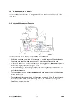
Detailed Descriptions
During printing, the horizontal motor (1) and drive belt (2) drive the carriage unit
(3) to the left and right on its guide rod (4) above the paper on the platen.
The HRB (5) behind the print head units relays signals to the control board from
the horizontal encoder sensor, DRESS sensor, color print heads and thermistors.
The COM board (6) relays signals between the main machine and the K1 print
head unit.
The horizontal encoder sensor (7) on the carriage unit brackets the horizontal strip
(8) and reads the codes on the top edge of the strip. This controls the operation of
the horizontal motor and movement of the carriage unit.
The thermistors (9) measure the temperature of the black (K1, K2) and color print
heads (C, YM). These temperature readings are used to adjust the voltage applied
to the piezoelectric elements above the nozzles that release ink during printing.
There is one piezoelectric element for each print head: K1 (10), K2 (11), C (12),
and YM (13). An electric charge applied to the element makes it expand and
discharge ink through the print head nozzles and onto the paper below.
At the beginning of a print job, the carriage moves left then back to the right, so
that the DRESS sensor (14) on the side of the carriage can detect the side edges
of the paper below. Based on these readings, the machine determines the image
print start position.
Ink level sensor 1 (15) checks the position of the feeler mounted on the side of the
K1 ink sub tank. Ink level sensor 2 (16) measures the positions of the feelers on
the sides of the K2, C, Y, and M sub tanks. The position of the feelers is used to
determine how much ink needs to be supplied. While ink level sensor 1 services
only the K1 print head unit, and ink level sensor 2 services the other four sub
tanks.
The temperature/humidity sensor (17) constantly measures the temperature and
Summary of Contents for D124
Page 1: ...D124 DETAILED DESCRIPTIONS MANUAL ...
Page 2: ......
Page 20: ...D124 14 Detailed Descriptions 1 2 GENERAL LAYOUT ...
Page 24: ...D124 18 Detailed Descriptions 1 4 MOTORS CLUTCHES AIR RELEASE SOLENOID ...
Page 28: ...D124 22 Detailed Descriptions 1 6 ORIGINAL PATH PAPER PATH SENSORS ...
Page 62: ...D124 56 Detailed Descriptions 3 1 2 SCAN JOB IMAGE DATA FLOW 3 1 3 PRINT JOB IMAGE DATA FLOW ...