


Detailed Descriptions
41
D124
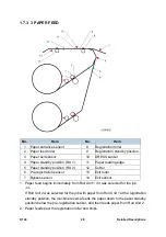
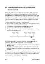
The original width sensors (1) detect the width of the original, and the original set
sensor (2) detects when the original is set by the operator.
The original entrance roller (3) feeds the original to the original registration sensor
(4). The original registration sensor detects the leading edge of the original and
stops long enough for the operator to align the original manually if the original is
not straight.
The CIS unit (5) under the original scans the original and sends the data to the SIB
in the scanner unit.
The original exit sensor (6) detects the leading and trailing edges of the original to
check the feed timing of the original.
The original exit roller (7) feeds the original out of the scanner unit.
The scanner motor (8) drives the scanner entrance roller and the exit roller via a
single timing belt.
Two safety micro-switches (not shown) on the left side of the scanner unit
disconnect power to the scanner unit every time the scanner unit cover is opened.
This prevents the CIS unit from switching on while the cover is open.
Pressing the original stop key
(a push-switch on the right side of the scanner
unit) interrupts scanning if a problem occurs during scanning (wrinkling, skew) so
that the original can be removed.
Summary of Contents for D124
Page 1: ...D124 DETAILED DESCRIPTIONS MANUAL ...
Page 2: ......
Page 20: ...D124 14 Detailed Descriptions 1 2 GENERAL LAYOUT ...
Page 24: ...D124 18 Detailed Descriptions 1 4 MOTORS CLUTCHES AIR RELEASE SOLENOID ...
Page 28: ...D124 22 Detailed Descriptions 1 6 ORIGINAL PATH PAPER PATH SENSORS ...
Page 62: ...D124 56 Detailed Descriptions 3 1 2 SCAN JOB IMAGE DATA FLOW 3 1 3 PRINT JOB IMAGE DATA FLOW ...


