


D124
120
Detailed Descriptions
4. Three selections are available for each feed station: Off (standard), Strong, and
Weak.
User Tool
Height
Sensor 1
Sensor 2
Off
Default
OFF
ON
Strong
2 mm
ON
ON or OFF
Weak
1 mm
OFF
OFF
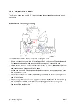
The illustration above shows the position of the actuator and status of the sensors for
selection.
The operator selects the setting in the User Tools (described above).
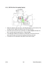
The horizontal motor drives the carriage unit to the right side of the machine where
the coupling of the lift motor engages the lift shaft. The lift cam (1) and actuator (2)
are attached to this shaft.
When the lift motor rotates the shaft, the actuator passes through the gaps of head
lift sensor 2 (3) and head lift sensor 1 (4).
When the actuator reaches the position for the selection [A], [B], or [C], the shaft
locks in place, and then the carriage moves away from the right side of the
machine. This disengages the shaft and lift motor couplings.
The cam keeps the carriage and print heads raised until the operator does the
procedure again to return them to the standard position.
Summary of Contents for D124
Page 1: ...D124 DETAILED DESCRIPTIONS MANUAL ...
Page 2: ......
Page 20: ...D124 14 Detailed Descriptions 1 2 GENERAL LAYOUT ...
Page 24: ...D124 18 Detailed Descriptions 1 4 MOTORS CLUTCHES AIR RELEASE SOLENOID ...
Page 28: ...D124 22 Detailed Descriptions 1 6 ORIGINAL PATH PAPER PATH SENSORS ...
Page 62: ...D124 56 Detailed Descriptions 3 1 2 SCAN JOB IMAGE DATA FLOW 3 1 3 PRINT JOB IMAGE DATA FLOW ...


