D124
170
Detailed Descriptions
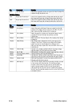
No.
Component
Function
S57
OCFS 4 (M)
On Carriage Fill Sensor M. The on-carriage sensor that
monitors the position of the feeler arm on the side of the M
ink sub tank. This sensor is used to signal low ink in the M
sub tank.
S58
Air Sensor: C
Detects air in the C ink sub tank of the C print head unit.
S59
Air Sensor: M
Detects air in the M ink sub tank of the YM print head unit.
S60
Air Sensor: Y
Detects air in the Y ink sub tank of the YM print head unit.
No.
Component
Function
Solenoid
SOL1
Air Release Solenoid
Located on the right side of the machine. When the air
level sensors detect excess air in an ink sub tank, the
system activates the plunger of the air release solenoid to
purge air from the tank. The partial vacuum created by the
suction pulls in the sides of the tank so that the tank can fill
with more ink.
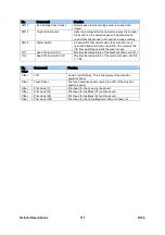
No.
Component
Function
Switches
SW01
Main Switch
Switches the machine on/off.
SW02
Front Cover Switch: Left
One of two safety switches that disable the machine when
the front cover is opened.
SW03
Front Cover Switch: Right
One of two safety switches that disable the machine when
the front cover is opened.
SW04
Cutter HP Switch (Right)
Detects when the cutter has arrived at the home position
on the right and switches the cutter off.
SW05
Cutter Return Switch (Left)
Detects when the cutter has arrived at the left side of the
machine after cutting. Reverses the cutter motor which
moves the cutter back to the home position on the right
side of the machine.
SW06
Paper Exit Guide Switch
Detects when the exit guide plate on the front of the
machine is opened and closed.
SW07
Roll Rewind Switch (RU1)
Located on the inside cover of the right end of Roll Unit 1.
Two presses rewinds the paper onto the paper roll.
SW08
Roll Rewind Switch (RU2)
Located on the inside cover of the right end of Roll Unit 2.
Two presses rewinds the paper onto the paper roll.
SW09
Front Cover Track Sensor
A push switch mounted on the left post of the main
machine that detects when the pin on the left end of the
front cover is mounted correctly in its track after the front
cover is closed. If the front cover is opened during a job,
this switch opens and brakes the carriage unit to slow it
down. The front cover open switches (which open slightly
later than the track sensor) stop the movement of the
carriage.
SW10
Ink Collector Cover Switch
Detects when the ink collector tank door is opened and
closed. The machine does not operate until the cover is
closed.
SW11
Horizontal Motor Interlock
Switch
A small switch attached to the top of the main power
switch. If the main power is switched off, this interlock
switch will keep the circuit closed until the horizontal motor
stops operating, and then it will open the circuit to switch
off the power. This ensures that the carriage unit is at rest
on the right side of the machine with the print heads
capped. (This causes a slight delay and a 2 minute
warning when the main power is switched off.)
Summary of Contents for D124
Page 1: ...D124 DETAILED DESCRIPTIONS MANUAL ...
Page 2: ......
Page 20: ...D124 14 Detailed Descriptions 1 2 GENERAL LAYOUT ...
Page 24: ...D124 18 Detailed Descriptions 1 4 MOTORS CLUTCHES AIR RELEASE SOLENOID ...
Page 28: ...D124 22 Detailed Descriptions 1 6 ORIGINAL PATH PAPER PATH SENSORS ...
Page 62: ...D124 56 Detailed Descriptions 3 1 2 SCAN JOB IMAGE DATA FLOW 3 1 3 PRINT JOB IMAGE DATA FLOW ...


