background image


DRUM 

SM 6-31 C264 

C26

6.6 DRUM 

6.6.1 OVERVIEW 


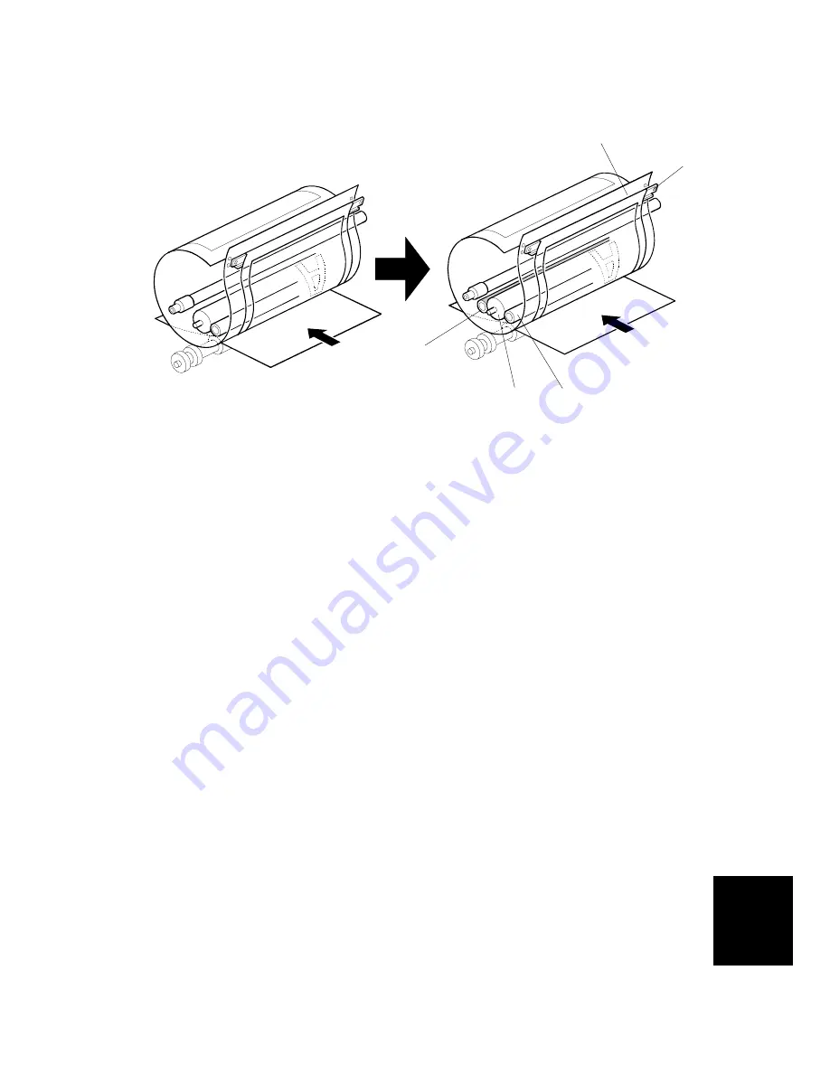
  The drum idling roller [C] ensures that the first print has sufficient ink density if 

the machine was not used for a long time. 


Procedure 

Ink is supplied inside the drum, through the drum shaft. 


The ink roller [A] and the doctor roller [B] spread the ink evenly on the screens. 
The drum idling roller [C] supplies ink to the screens and master before and after 
printing. 


Ink passes through the metal screen [D]. 


Ink passes through the cloth screen [E]. 


Ink passes through the holes in the master that were made by the thermal head. 


Ink reaches the paper. 

NOTE:

  1) The drum is driven by the main motor and turns only clockwise. 

2) The main motor speed and the drum stop positions are controlled by 

monitoring the motor encoder. 

3) The ink pump, which is outside the drum, supplies ink from the ink 

cartridge to the drum through the drum shaft. 

[A]

[B] 

[C]

[D] 

[E]

Summary of Contents for C249

Page 1: ...C249 C264 SERVICE MANUAL 001780MIU...

Page 2: ......

Page 3: ...C249 C264 SERVICE MANUAL...

Page 4: ......

Page 5: ...C249 C264 SERVICE MANUAL 001780MIU...

Page 6: ......

Page 7: ...RMISSION OF RICOH CORPORATION All product names domain names or product illustrations including desktop images used in this document are trademarks registered trademarks or the property of their respe...

Page 8: ......

Page 9: ...tion Users of this manual should be either service trained or certified by successfully completing a Ricoh Technical Training Program Untrained and uncertified users utilizing information contained in...

Page 10: ......

Page 11: ...RODUCT CODE COMPANY GESTETNER LANIER RICOH SAVIN C249 CP244 LDD145 JP4500 3560DNP C264 CP6244 LDD245 DX4542 3270DNP DOCUMENTATION HISTORY REV NO DATE COMMENTS 10 2003 Original Printing 1 09 2006 C264...

Page 12: ......

Page 13: ...NAL DRUMS 1 22 PREVENTIVE MAINTENANCE 2 PREVENTIVE MAINTENANCE 2 1 2 1 MAINTENANCE TABLE 2 1 REPLACEMENT AND ADJUSTMENT 3 REPLACEMENT AND ADJUSTMENT 3 1 3 1 GENERAL CAUTION 3 1 3 2 PRINT KEY START KEY...

Page 14: ...PREPARATION 3 29 3 9 2 CLOTH SCREEN 3 29 3 9 3 CLAMPER METAL SCREEN 3 31 3 9 4 INK PUMP ADJUSTMENT 3 33 3 9 5 INK ROLLER UNIT INK ROLLER ONE WAY CLUTCH 3 35 3 9 6 DOCTOR ROLLER GAP ADJUSTMENT 3 36 3...

Page 15: ...SP2 33 RE FEEDING SETTING 5 5 5 3 5 SP2 34 SLOW STARTING MODE 5 5 5 3 6 SP2 35 PRINTING PRESSURE ADJUSTMENT 5 5 5 3 7 SP2 36 INK IDLING ROLLER SETTING 5 6 5 3 8 SP2 38 IDLING AFTER PRINT SP2 28 29 5 6...

Page 16: ...NENT LAYOUT 6 1 6 1 2 ELECTRICAL COMPONENT LAYOUT 6 2 6 1 3 DRIVE LAYOUT 6 7 6 2 MASTER EJECT UNIT 6 8 6 2 1 OVERVIEW 6 8 6 2 2 MASTER CLAMPER OPENING MECHANISM 6 9 6 2 3 MASTER EJECT ROLLER MECHANISM...

Page 17: ...4 6 7 PAPER DELIVERY 6 46 6 7 1 OVERVIEW 6 46 6 7 2 PAPER DELIVERY UNIT DRIVE MECHANISM 6 46 6 7 3 PAPER SEPARATION FROM THE DRUM 6 47 6 7 4 EXIT PAWL DRIVE MECHANISM 6 48 6 8 TIMING CHART 6 49 6 8 1...

Page 18: ...C249 C264 vi SM PRINTER SCANNER C624 SEE SECTION C624 FOR DETAILED TABLE OF CONTENTS...

Page 19: ...RINTER CONTROLLER C624 REPLACEMENT AND ADJUSTMENT C249 TROUBLESHOOTING C249 SERVICE TABLES C249 DETAILED DESCRIPTIONS C249 SPECIFICATIONS C249 C264 TAB POSITION 2 TAB POSITION 1 TAB POSITION 3 TAB POS...

Page 20: ......

Page 21: ...INSTALLATION...

Page 22: ......

Page 23: ...right 1 1 2 ENVIRONMENTS TO AVOID 1 Locations exposed to direct sunlight or strong light more than 1 500 lux 2 Dusty areas 3 Areas containing corrosive gases 4 Locations directly exposed to cool air...

Page 24: ...INSTALLATION REQUIREMENTS C249 1 2 SM 1 1 4 MACHINE ACCESS Place the machine near a power source providing clearance as shown below C249I000 WMF...

Page 25: ...ALLATION PROCEDURE 1 2 1 MAIN UNIT Accessory Check Make sure that you have all the accessories listed below Description Q ty 1 Master Spool 2 2 Operating Instructions 1 3 NECR Ricoh version only 1 4 M...

Page 26: ...ed with the table CAUTION Only lift with the carrying handles on the bottom corners of the machine Secure the machine on the table with the 2 screws A provided This prevents the machine from falling f...

Page 27: ...INSTALLATION PROCEDURE SM 1 5 C249 Installation 2 Remove the filament tape and string securing the covers and units as shown above C249I907 WMF C249I020 WMF C249I908 WMF C249I909 WMF...

Page 28: ...y bag A 4 Insert both spools into a new master roll 5 Install the master roll as shown to the right 6 Insert the leading edge of the master roll under the platen roller The arrows B indicate the corre...

Page 29: ...Set the master making unit 9 Open the door and insert a new ink cartridge D 10 Open the paper table and load a stack of paper 11 Make sure that the side plates E touch the paper gently Shift the lock...

Page 30: ...plate and adjust them to the paper size 14 Firmly insert the power plug in the outlet 15 Make sure that the wall outlet is near the machine and easily accessible 16 Turn on the main switch H 17 Press...

Page 31: ...ss Roller during transport Please be sure to remove the tape A sponge B and tag C by pulling the portion shown in the illustration toward the front of the machine before beginning machine operation NO...

Page 32: ...ER INSTALLATION OPTION Accessory Check Check the quantity and condition of the accessories in the box against the following list Description Q ty 1 Stepped Screw 2 Installation Procedure 1 Install the...

Page 33: ...ries in the box against the following list Description Q ty 1 Stepped Screw 2 2 Screws 3 3 Screwdriver 1 4 DF Exposure Glass 1 5 Decal Exposure Glass 1 6 Decal Scale mm 1 7 Decal Scale inch 1 8 Scale...

Page 34: ...he lower front side as shown 4 Peel off the backing D of the double sided tape attached to the rear side of the scale guide E then install the scale guide 2 screws removed in step 2 5 Install the two...

Page 35: ...al K as shown 10 Plug in the power cord then turn the main switch on 11 Make a full size copy using the ADF Then check to make sure the side to side and leading edge registrations are correct If they...

Page 36: ...1 Attach the two stabilizer brackets A to the back of the table using the thumbscrews 4 screws 2 Attach the caution label B as shown CAUTION This procedure must be done to prevent the machine from fal...

Page 37: ...ob Screw C210 C217 C218 C219 C222 C223 C225 C228 C231 C237 C238 C247 C248 and C249 only 2 2 Screw M4 x 25 C211 C212 C213 C214 C216 C224 and C226 only 2 3 Hexagon Nut M4 C211 C212 C213 C214 C216 C224 a...

Page 38: ...ect the tape marker cable to the main body 4 Install the auxiliary bracket B C5326502 on the tape marker with M4 x 8 screws accessories C NOTE Install the lock washer E accessories with the lower of t...

Page 39: ...nnect the tape marker cable to the main body 5 Install the tape marker on the main body with two knob screws B accessories in the two outer holes in the tape marker bracket NOTE 1 Tighten the knob scr...

Page 40: ...es 4 Reinstall the rear cover 5 Install the auxiliary bracket B on the main body with the hexagon nut D accessories as shown NOTE Install the lock washer C accessories with the nut Tape Marker 6 Insta...

Page 41: ...e two outer holes in the tape marker bracket NOTE 1 Install the lock washer B accessories with the lower of the two knob screws 2 Tighten the knob screws with a screwdriver to prevent them from coming...

Page 42: ...e marker on the main body with two knob screws A accessories in the two inner holes of the tape marker bracket NOTE 1 Install the lock washer B accessory with the lower of the two knob screws 2 Tighte...

Page 43: ...the tape entrance until it stops as shown in the illustration E NOTE Be sure that the tape is installed in the proper direction If it is not the tape marker will not work correctly 3 Turn on the main...

Page 44: ...drum case The decal must be the same color as the ink in use 4 Remove the drum unit 5 Leave the master wrapped around the removed drum to protect the drum from dust and from drying 6 Keep the removed...

Page 45: ...PREVENTIVE MAINTENANCE...

Page 46: ......

Page 47: ...l C C C C Dry Cloth Platen Cover White Plate C C C C Damp Cloth Exposure Glass C C C C Dry Cloth Master Feed Thermal Head C Alcohol Platen Roller C C C C Damp cloth and water Master Eject Rollers C C...

Page 48: ...Drive Gears and Cam D L L L Grease Alvania 2 Ink Pump Gears E L L L Motor Oil SAE 20 In Outside of Drum C C C C Alcohol Ink Nozzle C C C C Alcohol Black Patch G C C C C Dry Cloth Others Main Drive Ti...

Page 49: ...REPLACEMENT AND ADJUSTMENT...

Page 50: ......

Page 51: ...CAUTION CAUTION Turn off the main power switch and unplug the machine before attempting any of the procedures in this section NOTE This manual uses several symbols The meaning of those symbols are as...

Page 52: ...COVERS BOARDS C249 3 2 SM 3 3 COVERS BOARDS 3 3 1 FRONT COVER PANEL A Front door x 4 B Front cover x 6 C Upper right cover x 2 D Operation panel x 4 x 1 C238R006 WMF B A C D...

Page 53: ...over x 2 D Rear upper cover 3 3 3 MPU Rear left cover Rear right cover 3 3 2 A MPU x 17 x 6 9 clamps CAUTION Move the RAM B from the old board to the new one so that the SP mode settings will be trans...

Page 54: ...Upper left cover 3 3 2 Master eject unit 3 5 1 A PSU x 5 x 2 2 clamps CAUTION When the PSU is replaced the thermal head voltage returns to the default Adjust the thermal head voltage 3 6 6 after inst...

Page 55: ...4 1 EXPOSURE GLASS SCALES A Left scale x 2 B Upper scale x 3 C Exposure glass 3 4 2 SBU AND LAMP STABILIZER SCANNER MOTOR Left scale Upper scale Exposure glass 3 4 1 Upper right cover 3 2 1 A SBU cov...

Page 56: ...r x 2 x 1 1 spring 3 4 3 SCANNER H P SENSOR PLATEN COVER SENSOR Left scale Upper scale Exposure glass 3 4 1 Operation panel 3 3 1 Rear upper cover 3 3 2 A Platen cover sensor x 1 B Left stay x 1 C Sca...

Page 57: ...the opening in the frame Exposure glass 3 4 1 1 Left stay 3 4 3 A Platen base x 1 x 5 B Rear frame x 1 x 2 C Front frame x 5 D Exposure lamp x 1 NOTE After installing the lamp press the lamp holder E...

Page 58: ...he new scanner wire around the pulley as shown then temporarily secure the pulley with tape 2 Re install the first scanner Then secure the first and second scanner with the scanner positioning pins P...

Page 59: ...tension bracket F 10 Secure the scanner drive pulley G 1 Allen screw 11 Remove the scanner positioning pins I P N A0069104 12 Slide the scanner to the left and right several times then set the scanner...

Page 60: ...in the order given below SP6 10 Master writing speed 5 7 3 SP6 21 Paper registration position 5 7 3 SP6 05 Scanning speed platen 5 7 3 SP6 06 Scanning speed ADF SP6 03 Scanning start position platen...

Page 61: ...MASTER EJECT SM 3 11 C249 Replacement Adjustment 3 5 MASTER EJECT 3 5 1 MASTER EJECT UNIT A Master eject unit x 1 x 2 1 clamp C249R001 WMF A...

Page 62: ...plug Then turn on the main switch to access SP mode 2 Select SP5 74 T H driving motor up then press the enter key and turn off the main switch NOTE 1 The thermal head is released after about 2 second...

Page 63: ...13 C249 Replacement Adjustment Master making unit 3 6 1 Open the platen roller unit 1 A T H upper cover x 2 B T H side cover x 1 Close the platen roller unit 1 C Thermal head x 2 C249R049 WMF C249R12...

Page 64: ...head clockwise and remove a nail 2 Turn the thermal head counterclockwise and remove a nail 3 Remove the thermal head slowly NOTE If you cannot access SP modes open the master making unit and loosen...

Page 65: ...e Make sure to follow the above procedure or the thermal head will not be installed correctly 1 Fit the base s springs A over the protrusions B on the underside of the thermal head 6 points 2 While fi...

Page 66: ...249 3 16 SM 3 6 3 DUCT PLATE HP SENSOR DUCT PLATE MOTOR Master making unit 3 6 1 A Rear cover x 2 B Duct plate HP sensor x 1 x 1 C Rear rail bracket x 2 D Duct plate motor x 1 x 2 C249R101 WMF C249R10...

Page 67: ...ent Adjustment 3 6 4 CUTTER UNIT A Cutter unit x 1 x 1 3 6 5 THERMAL HEAD DRIVING UNIT Thermal head 3 6 2 Rear cover 3 3 2 Cutter unit 3 6 4 A Anti Static roller x 2 B Thermal head driving unit x 2 x...

Page 68: ...turn VR1 clockwise rapidly while the master making unit is connected The T H will be damaged if too much voltage is supplied suddenly 2 Connect the positive terminal of a circuit tester to TP701 and...

Page 69: ...g iron base 3 Connect the power plug and turn on the main switch to access SP mode 4 Select SP6 52 Duct jam sensor voltage 5 Press the Print Start key 6 Measure the voltage and turn VR102 so that the...

Page 70: ...y 5 Pull out the master making unit from the machine and open the master set cover 6 Insert the leading edge of the master under the master tension roller then close the master set cover and reinstall...

Page 71: ...VR104 so that the value becomes between 0 1 and 0 1 volts from the standard value 2 0 volts 6 Turn off the main switch then remove the master that is wrapped around the drum and install the drum in t...

Page 72: ...used master roll inside the master making unit and close the master making unit NOTE Detect a low fiber content paper side of a piece of paper to the master end sensor 4 Connect the power plug and tur...

Page 73: ...23 C249 Replacement Adjustment 3 7 PAPER FEED 3 7 1 PICK UP ROLLER PAPER FEED ROLLER FRICTION PAD Lower the paper table A Pick up roller x 1 B Paper guide x 1 C Feed roller x 1 D Friction pad E C249R...

Page 74: ...mooth printing paper separation Default The next position to the top Adjust the paper separation pressure by loosening and moving the adjusting screw A up or down Moving up the screw Increases the pap...

Page 75: ...acement Adjustment 3 7 3 PAPER WIDTH DETECTION BOARD Lower the paper table A Paper table x 1 x 2 B Table cover x 5 3 washers C Sensor cover x 2 D Paper width detection board x 1 x 1 C238R018 WMF C238R...

Page 76: ...f the printing pressure release arms disengage the press roller will be pulled upwards suddenly Remove the drum A Press roller x 1 The bearings on the rear and front differ During installation ensure...

Page 77: ...lowest position This is when the high points of the cams on the drum flanges meet with the cam followers on both ends of the press roller To find out the correct position of the drum for the adjustmen...

Page 78: ...Improves print results without decreasing the run length Standard Within 17 0 2 mm 1 Adjust the distance A to 17 0 2 mm by turning the adjusting bolt B 2 Repeat the same procedure for the printing pr...

Page 79: ...ink detection to OFF and feed paper until ink ends After finishing the required procedures in this section do not forget to return SP2 10 to the default ink detection on 3 9 2 CLOTH SCREEN Remove the...

Page 80: ...he correct side of the screen is facing up In addition make sure that the stays for securing the cloth screen are positioned correctly Refer to the upper right illustration When replacing the cloth sc...

Page 81: ...e inside of the clamping plate C If it is dirty with ink the master may slip off and the image position on the prints will move toward the trailing edge of the prints during a printing run 2 Use a clo...

Page 82: ...appearance Be careful not to mix them up or use the wrong screws When installing the metal screen secure the trailing edge first with the 2 screws Then tighten the other screws while removing the slac...

Page 83: ...der Remove the drum A Lower pump cover x 2 B Upper pump cover x 3 1 Remove the E ring C to free the plunger from the pump drive slider D 2 Loosen the two screws securing the holder E Do not remove the...

Page 84: ...oth 5 If the motion is stiff loosen the pump screws G and adjust the pump position 6 After tightening repeat step 4 and step 3 7 Re tighten the two screws H 8 Check that the piston motion is smooth 9...

Page 85: ...ER ONE WAY CLUTCH Metal screen 3 9 3 Pump covers 3 9 4 A Board cover x 2 B Front stay x 2 x 3 C Front flange D Rear stay x 2 E Rear stoppers x 1 F Ring G Rear flange H Ink roller unit I Ink roller one...

Page 86: ...Make sure that a 0 08 mm gap gauge goes through the gap A between the ink and doctor rollers and that a 0 10 mm gap gauge does not NOTE 1 The gap should be checked at both ends of the doctor roller In...

Page 87: ...detection on SP6 40 Ink detection adjustment 5 7 2 3 9 8 MAIN MOTOR PULLEY POSITION After putting the pulley back on the main motor shaft refer to the above illustration for the correct position of t...

Page 88: ...DRUM C249 3 38 SM 3 9 10 INK IDLING MOTOR INK IDLING ROLLER HP SENSOR Cloth Screen 3 9 2 Clamper Metal Screen 3 9 3 A Ink idling roller HP sensor x 1 x 1 B Ink idling motor x 1 x 2 C249R106 WMF A B...

Page 89: ...in this order do not remove them Make sure that the bracket C becomes free from engagement and the cam follower D contacts the drum flange 2 Using a gap gauge measure the clearance E between the drum...

Page 90: ...comes free from engagement and the cam follower E contacts the drum flange 3 Measure the gap F between the cam follower and cam face front drum flange It should be 0 to 0 5 mm 4 If the gap is not corr...

Page 91: ...APER DELIVERY UNIT A Paper delivery cover x 4 B Paper delivery unit x 3 x 2 3 10 2 DELIVERY BELT PAPER EXIT SENSOR Paper delivery unit 3 10 1 A Paper guide x 2 B Delivery belts C Vacuum fan motor x 1...

Page 92: ...n this order do not remove them Make sure that the bracket C becomes free from engagement and the cam follower D contacts the drum flange 7 Using a gap gauge measure the clearance E between the drum s...

Page 93: ...he bracket D becomes free from engagement and the cam follower E contacts the drum flange 9 Measure the gap F between the cam follower and cam face front drum flange It should be 0 to 0 5 mm 10 If the...

Page 94: ...Rear covers 3 3 2 1 Check the recess in the drum drive gear meets the positioning hole A in the bracket as shown 2 Check whether the hole B in the pump drive gear is aligned with the hole C in the air...

Page 95: ...49 Replacement Adjustment 3 11 SPECIAL TOOLS The following are the special tools used for service Description Part number Note Scanner positioning pins 4 pins as a set A006 9104 3 4 5 Flash memory car...

Page 96: ......

Page 97: ...TROUBLESHOOTING...

Page 98: ......

Page 99: ...N E 09 Thermal Head Thermistor Open The thermistor output voltage is over 4 9 volts Thermal head thermistor Thermal head connector E 10 Thermal Head Energy Pulse error The CPU detects an abnormal ID s...

Page 100: ...D error The CPU detects an abnormal ID signal from the thermal head Thermal head MPU Thermal head connector disconnected E 41 Idling roller HP sensor remains on or off The idling roller HP sensor does...

Page 101: ...Drum Master Sensor Open The D jam indicator is lit whenever a master is made Shorted Paper Exit Sensor Open The C jam indicator is lit Shorted The B jam indicator is lit whenever a copy is made Master...

Page 102: ...m indicator will be lit Shorted The load more paper indicator is lit Cutter HP Sensor Open The cutter cuts the master only half way and the D jam indicator is lit Shorted E 01 is displayed Paper Lengt...

Page 103: ...ators are lit Open Master making begins nevertheless the lower master tray is open and master vacuum fans does not absorb a master and E 01 is displayed Lower Master Tray Set Switch Shorted The Lower...

Page 104: ...ly this LED is blinking at intervals of 2 seconds LED102 Not used LED103 Monitors the CPU operation Usually this LED is blinking at intervals of 1 second LED104 Monitors the master end sensor When the...

Page 105: ...rum A4 black drum SW1 OFF OFF ON SW2 OFF ON OFF SW3 OFF OFF OFF SW4 OFF OFF OFF 4 3 5 TEST POINTS MPU No Function TP101 Measures the master end sensor voltage 3 6 10 TP102 Measures the duct jam sensor...

Page 106: ...below Then set the paper in the paper feed tray correctly C249T903 WMF Feed pressure is set as thin paper O I Operation Printing on thick or thin paper Separation pressure is set as strong 6 7 3 Use...

Page 107: ...ct Caution Once this has been changed the registration position will be out of order The position of registration is not correct Adjust SP6 21 the paper registration position 5 7 3 Shift paper registr...

Page 108: ...ss roller The gap between the press roller and paper delivery unit is too big Attach paper guide sheet at the vacuum fan Paper stuck is bad The positions of paper delivery side plates and end plate ar...

Page 109: ...lution Does not supply ink Ink detection board not working Broken ink detecting pins Make sure SP2 10 ink detection is ON Clean the ink detecting pins Adjust ink detection volume 5 7 2 Change ink dete...

Page 110: ...gap 3 9 6 Shift paper registration The position of registration is not right Adjust SP6 21 the paper registration position 5 7 3 Ink is on the paper s leading edge The point of paper tears master Enve...

Page 111: ...stall the RAM which was on the old MPU to the new MPU Be sure to do VR adjustments for sensors etc 3 3 3 Due to static electricity Make sure the machine is secure A fixed screw acts as a ground The ma...

Page 112: ...ent of thermal head printing pressure voltage Harness and short circuit defective signal system Defective MPU board Cause scanner Defective exposure lamp Defective SBU board Defective MPU board Cause...

Page 113: ...section Refer to master eject section Refer to paper delivery section OK Poor image skew paper shift image Poor paper feed Poor drum Others Cause paper feed Wrong amount of bend for registration The...

Page 114: ......

Page 115: ...SERVICE TABLES...

Page 116: ......

Page 117: ...epresentatives for any reason data might be deleted or settings might be changed In such case product quality cannot be guaranteed any more 5 1 USING SERVICE PROGRAM MODES Use the service program mode...

Page 118: ...zoom keys enter the desired sub menu number then press the Enter key or the OK key 3 Enter the desired value or mode using the number keys SP modes are listed in the service program tables NOTE 1 Use...

Page 119: ...7 P original feed in jam 6 8 2 1 58 P original feed out jam 6 8 2 1 59 D master feed jam 6 8 3 1 60 D master cut jam 6 8 3 1 61 D master duct jam 6 8 3 1 70 Main firmware part number 5 2 2 1 71 I O RO...

Page 120: ...2 Master counter and print counter 2 28 Idling after less then 3 prints ver 3 09 Off Off On 5 3 8 2 29 Idling after x no of prints ver 3 09 1 to 5 5 3 8 2 31 Ink Auxiliary Supply Not used 0 0 After 1...

Page 121: ...this SP mode to OFF ON Re feeding is on factory setting OFF Re feeding is off 5 3 5 SP2 34 SLOW STARTING MODE Increase the image density of trial prints The figures below are drum rotating speeds A se...

Page 122: ...tes and you can select the number of prints 1 to 5 by setting SP2 29 5 3 9 SP2 41 2 42 THERMAL HEAD ENERGY CONTROL 2 41 The default is 7 This means that during normal printing mode the thermal head en...

Page 123: ...r feed table return to the lower standard standby position even if SP2 95 is ON This is to make sure that the master making unit does not touch the paper feed table When the Master End condition occur...

Page 124: ...er Example 2003 January 27th 13 00 00 03 01 27 13 00 00 OK 5 4 3 SP3 4 INPUT INSTALLATION DATE Input installation date in that order Press the Enter key between each one Input the last two digits of t...

Page 125: ...e plate limit SN 4 69 ADF open sensor 4 18 Ink detection signal 4 19 Color drum signal 4 70 Key counter signal 4 20 A4 drum signal 4 21 Drum set signal 4 80 Master edge sensor 4 22 Clamper open sensor...

Page 126: ...0 rpm 5 71 Master push Mylar push 5 19 Main motor 75 rpm 5 72 Master push Mylar free 5 20 Main motor 90 rpm 5 73 Cutter motor reverse 5 21 Main motor 105 rpm 5 74 T H driving motor up 5 22 Main motor...

Page 127: ...1 SBU calibration Start with key 5 7 4 6 32 MTF filter Letter M 1 0 to 7 5 7 5 6 33 MTF filter Letter S 1 0 to 7 5 7 5 6 34 MTF filter Letter Photo M 4 0 to 7 5 7 5 6 35 MTF filter Letter Photo S 4 0...

Page 128: ...rpm 0 40 to 40 6 112 Paper Regist skip 75 rpm 0 40 to 40 6 113 Paper Regist skip 90 rpm 0 40 to 40 6 114 Paper Regist skip 105 rpm 0 40 to 40 6 115 Paper Regist skip 120 rpm 0 40 to 40 6 116 Paper mi...

Page 129: ...st skip A4 120 Not used 0 40 to 40 6 148 Paper middle bulge A4 15 Not used 0 100 to 100 6 149 Paper middle bulge A4 30 Not used 0 100 to 100 6 150 Paper middle bulge A4 45 Not used 0 100 to 100 6 151...

Page 130: ...the door cover Then turn the VR1 A on the ink detection board until the display becomes 3 0 u 3 s NOTE When the drum has ink inside the machine displays 5 7 3 IMAGE ADJUSTMENT SP6 10 21 5 3 AND 1 Adju...

Page 131: ...place Example If the value is 133 130 133 130 x 100 2 3 5 Access SP6 10 input the calculated ratio and press the Enter key 6 Repeat the procedure to make sure that the ratio is correct SP6 21 Paper r...

Page 132: ...art position ADF 1 Make copies of the test pattern printed during the previous adjustments previous page in platen mode at 90 rpm speed 3 Use the 10th print for the adjustment 2 The space between the...

Page 133: ...ts of paper on the exposure glass 2 Access SP6 31 and then press the Enter key to start the auto calibration 5 7 5 SP6 32 TO 37 MTF FILTER Sharpens image however moir can become more apparent Refer to...

Page 134: ...on will be correct 5 7 7 SP6 60 MASTER RETURNING VALUE The master registration value can be made exact by adjusting the amount of master feeding after detecting the leading edge of master This is done...

Page 135: ...k temperature check a value of the ink temperature 4 Make 6 copies at speed 5 finishing with 120 rpm Perform the adjustment below for all 6 copies Trail print 30 rpm 1st print 45 rpm 2nd print 60 rpm...

Page 136: ...ecomes and vice versa Also each step corresponds to approximately 0 58mm Input the value that will bring the distance to 8mm 7 Perform the adjustment again for any of the samples that are still outsid...

Page 137: ...pm Perform the adjustment below for all 6 copies Trail print 30 rpm 1st print 45 rpm 2nd print 60 rpm 3rd print 75 rpm 4th print 90 rpm 5th print 105 rpm 6th print 120 rpm NOTE When values of the ink...

Page 138: ...105 and 120 rpm samples Higher values C Blurred images improve doubled images tend to be more noticeable Lower values D Doubled images improve blurred images tend to be more noticeable 7 Perform the...

Page 139: ...rpm Perform the adjustment below for all 6 copies Trail print 30 rpm 1st print 45 rpm 2nd print 60 rpm 3rd print 75 rpm 4th print 90 rpm 5th print 105 rpm 6th print 120 rpm NOTE When values of the ink...

Page 140: ...the doubled or blurred images range 90 to 8 step 1 for each of 6 copies samples i e 30 60 75 90 105 and 120 rpm samples Higher values C Blurred images improve doubled images tend to be more noticeable...

Page 141: ...t Settings 7 1 Factory settings clear Hold 0 push to clear 5 8 2 7 3 Total counter clear Hold 0 push to clear 7 4 Jam Error data clear Hold 0 push to clear 5 8 2 SP7 1 FACTORY SETTINGS CLEAR This rese...

Page 142: ...cators on the panel Active when start press 8 31 Not used Off Off On 5 9 2 SP8 1 DOWNLOAD MAIN FIRMWARE Upgrades the main firmware using a flash memory card 1 Before downloading new firmware check the...

Page 143: ...not use them except the number 6 1 Grid 2 Vertical 3 Horizontal gray 4 Vertical gray 5 16 grays 6 Cross 7 Diagonal grid 8 256 grays 9 64 grays 5 9 5 SP8 21 PAPER FEED TEST 15 RPM Feeds paper at the l...

Page 144: ...operation panel appears as a negative image See the illustration below Normal Image Negative Image NOTE Set SP 8 18 OFF after you repair inspect the machine Additional explanation Security Mode is use...

Page 145: ...DETAILED DESCRIPTIONS...

Page 146: ......

Page 147: ...ller 8 Master Roll 9 Thermal head 10 Paper separation roller 11 Paper feed roller 12 Paper table 13 Registration rollers 14 Doctor roller 15 Ink roller 16 Press roller 17 Idling roller 18 Exit pawl 19...

Page 148: ...M 6 1 2 ELECTRICAL COMPONENT LAYOUT C249D939 WMF C249D064 WMF 30 32 33 34 35 36 37 38 39 40 41 42 43 44 45 46 47 48 49 50 51 31 52 53 54 55 59 26 27 28 1 2 3 6 5 4 7 9 8 10 12 11 14 15 17 18 19 20 21...

Page 149: ...MECHANISM OVERVIEW SM 6 3 C249 Detailed Descriptions C249D940 WMF C249D941 WMF 62 60 61 64 65 66 67 63 69 70 68...

Page 150: ...ject Motor Sends used masters into the master eject box 35 Air Knife Fan Motor 1 Rotates the fan to provide air to separate the leading edge of the paper from the drum 36 Air Knife Fan Motor 2 41 Pres...

Page 151: ...Open Sensor Detects if the clamper is in the open position 45 Clamper Closed Sensor Detects if the clamper is in the closed position 49 Table Lower Sensor Detects when the paper table is at its lower...

Page 152: ...lease Solenoid Releases the press roller to apply printing pressure Counters No Component Function 25 Paper Counter Keeps track of the total number of copies 26 Master Counter Keeps track of the total...

Page 153: ...ssure plate motor 2 Clamper motor 3 Paper delivery motor 4 Main motor 5 Registration motor 6 Table motor 7 Paper feed motor 8 Master feed motor 9 Scanner motor 10 Thermal head driving motor 11 Duct pl...

Page 154: ...edge and feed the master for 1 0 s into the master eject box C The clamper then closes The drum then turns at 30 rpm while the master eject rollers continue to feed the used master into the eject box...

Page 155: ...tart key is pressed and before the clamper motor starts the master eject position sensor I is checked the drum must be at the master eject pos 2 The sensor actuators on the link C the clamper open sen...

Page 156: ...on for 1 0 s to pick up the leading edge 2 Then the clamper motor reverses to close the clamper 3 The drum then starts turning at the slower speed 30 rpm At the same time the master eject rollers turn...

Page 157: ...ion the pressure plate motor turns until the actuator on the pressure plate actuates the limit sensor D 2 After master making and cutting the motor reverses until the pressure plate home position sens...

Page 158: ...ird mirror F Lens The exposure lamp is a xenon lamp DC 24V Light reflected off the original is directed onto a CCD via the mirrors and the lens The main scan resolution is 600 dpi because the CCD is 6...

Page 159: ...450 pixels and the resolution is 600 dpi 23 6 lines mm The A D converter in the SBU transforms the analog signals into 8 bit digital signals The MPU carries out the following processes on the image d...

Page 160: ...Letter Letter Photo Photo and Tint This model has SP mode adjustments 6 3 5 SMOOTHING FILTER The Smoothing filter enhances the desired image qualities The Smoothing filter is used in Photo mode only T...

Page 161: ...ch pixel value to a higher number is selected This ensures accurate generation of the 256 gray scales from black to white 6 3 8 FINE MODE Purpose Use this function to make clear prints This machine s...

Page 162: ...d protection The thermistor on the thermal head provides thermal head protection preventing the thermal head from overheating when processing a solid image The CPU checks for any abnormal condition wh...

Page 163: ...horizontal and firmly reconnect them Do not touch the connector terminals with bare hands to prevent damage from static electricity Master Platen Roller Adjust the voltage supplied to match the speci...

Page 164: ...master to the drum Procedure The machine feeds the master from the master roll A The thermal head B makes an image on the master Clamper C opens The drum is at the master feed position The clamper cla...

Page 165: ...otor B turns on 1 The master feed motor feed the master 40 mm when the master edge sensor C does not detects the master 2 1 If the master edge sensor detects the master the master feed motor does not...

Page 166: ...se cam C Thermal head base D is released from the platen roller E Thermal head HP sensor F has two stop positions Platen roller apply position Platen roller release position The actuator disk G interr...

Page 167: ...er duct A by the three duct fans B as the thermal head transfers the image to it The stored master is fed out from the duct when the drum reaches the master making position after the used master has b...

Page 168: ...A Duct jam sensor The duct jam sensor A detects whether there is a master in the lower master tray or not When the duct jam sensor detects master the D jam indicator comes If this happens open the low...

Page 169: ...e duct plate C moves The duct plate motor HP sensor D has four stop positions The duct plate close position The duct plate middle position The duct plate open position The master push mylar apply posi...

Page 170: ...to the open position when the clamper clamps the master At this time the master is stored in the master buffer duct D 4 The duct plate moves the master push mylar E after the clamper clamps the maste...

Page 171: ...n the tension roller releases and the master is fed to the clamper on the drum For details of the tension roller see the next section 3 After the clamper closes the master feed motor feeds the master...

Page 172: ...een ejected the drum is stopped at the master feed position The master clamper clamps the leading edge of the new master before the drum starts to turn again The tension roller H normally presses agai...

Page 173: ...B The master push mylar C contacts with the master on the drum The master push mylar contacts with the master on the drum to distribute ink through the master The 2nd drum master D sensor prevents the...

Page 174: ...or detects black patch on the clamper C even if there is a master on the drum The master push mylar D contacts with the master E on the drum A 2nd drum master sensor B Black patch on the screen C Blac...

Page 175: ...e rear because of the two different spiral threads on the screw shaft The cutter usually cuts a master of about 550 mm in length The cutter cuts a master of about 340 mm in length when an optional A4...

Page 176: ...on sensor drum HP signal within 5 0 seconds after the main motor turns on by master cut miss the cutter tries to cut the master again The cutter cuts the master a second time and the jam indicator lig...

Page 177: ...drum idling roller C supply ink to the screens and master before and after printing Ink passes through the metal screen D Ink passes through the cloth screen E Ink passes through the holes in the mast...

Page 178: ...monitors the pulses and controls the drum speed and stop positions 3 The drum has four sensors Master eject position sensor D master eject position and HP Feed start sensor E feed start timing Second...

Page 179: ...r rotation converted into piston motion Supplies ink from the ink cartridge to the ink roller via the pump the shaft the tube and the ink distributor pipes C Ink drops through 4 openings D in the ink...

Page 180: ...tch to prevent the ink roller from being turned in reverse if the drum is manually turned in reverse 2 The ink roller does not touch the metal screen when the machine is not printing 3 During printing...

Page 181: ...ler C 2 If the pins detect an insufficient amount of ink after activating the ink pump motor for 30 seconds a no ink condition is detected The add ink indicator on the operation panel will light 3 The...

Page 182: ...rs the drum idling mode before and after printing This ensures that the first print has sufficient ink density even if the machine was not used for a long time The idling roller motor A turns to press...

Page 183: ...Low below 15degree 0 2 3 3 6 5 7 DETECTION OF MASTERS ON THE DRUM A Drum master sensor B Black patch on the screen C Black patch on the clamper The drum master sensor A detects whether there is a mast...

Page 184: ...le is lifted The pick up roller A picks up a sheet of paper The feed roller B and the separation pad C only allow one sheet to pass The registration rollers D feed the paper The print is made NOTE 1 A...

Page 185: ...oller system Handling Paper Paper Feed Paper Feed Methods Friction Pad 2 When the rollers stop and paper is fed by the registration rollers the one way clutches in the pick up and feed rollers ensure...

Page 186: ...ly occur the lever should be moved to the left or the right to adjust the pressure If non feed or multi sheet feed problems still occur the paper separation pressure can also be adjusted This should b...

Page 187: ...ration motor start timing is changed Registration Roller Up Down Mechanism After the printing paper is caught between the drum and the press roller the registration motor stops and the upper registrat...

Page 188: ...tension from the springs E when the cam followers F come off the high points of the cams G During the printing cycle the solenoids stay on However if paper does not reach the registration sensor H at...

Page 189: ...SP6 70 to 87 5 7 1 Temperature Print Speed Low Below 150 C Normal 150 to 280 C High 280 C and above Trial Print Printing Pressure 2 Printing Pressure 2 Printing Pressure 2 1st Print 60 rpm Printing P...

Page 190: ...ops 2 When the table lower sensor F is actuated the tray has been lowered to its lower limit and the motor stops 3 During a printing run sheets are fed from the stack lowering the pick up roller When...

Page 191: ...ack and pinion mechanism There is a lock lever B to hold the side fences in position Side fence friction pads The two side fence friction pads C are included as accessories These are not used normally...

Page 192: ...D The paper exit sensor E is used for jam detection 6 10 6 6 7 2 PAPER DELIVERY UNIT DRIVE MECHANISM Mechanism Paper delivery motor A Belt B Shaft C Rotates the transport belts D NOTE 1 The vacuum fan...

Page 193: ...key is pressed or when master cutting is finished The paper passes under the exit pawl and is delivered to the delivery table Exit pawl air pump Drive from the main motor is transmitted to the pump g...

Page 194: ...flange the exit pawl closely approaches the drum surface due to the tension from a spring G As the master clamper approaches the exit pawl the high point of the drum flange cam C moves into contact w...

Page 195: ...art Timing Sensor Main Motor Clamper Closed Sensor Clamper Motor Pressure Plate Limit Sensor Pressure Plate HP Sensor Pressure Plate Motor Master Eject Position Sensor HP Clamper Open Sensor Master Ej...

Page 196: ...the clamper opens for 1 0 seconds the clamper motor turns to close the clamper 4 The clamper closes 5 When the clamper is closed the main motor turns on 6 The drum is at the feed start timing sensor...

Page 197: ...d Motor Cutter HP Sensor Duct Plate Motor Cutter Motor Duct Plate HP Sensor Duct Fan Motors Blower Fan Motor Thermal Head Driving Motor Thermal Head HP Sensor Master Eject Position Sensor Clamper Open...

Page 198: ...6 When the master feed motor has fed the master 430 mm the main motor turns on 7 The duct plate motor turns to contact with the master push mylar to the master on the drum 8 When the master feed moto...

Page 199: ...m Fan Motor Air knife Fan Motor Registration Sensor Printing Pressure HP Sensor Printing Pressure Motor Pressure Release Solenoid Paper Feed Motor Registration Motor Trial Print Stop delay delay The p...

Page 200: ...eject position sensor the printing pressure motor turns on 6 After the drum is at the feed start timing sensor plus feed delay time the paper feed motor turns on 7 After the feed start timing sensor...

Page 201: ...master the B jam indicator will light Compressing the used master Jam check timing When moving the pressure plate Check If the master eject sensor detects a master when the pressure plate limit sensor...

Page 202: ...the original Jam check timing During original feed out Check 2 When the DF has fed the original length plus 80 mm the DF registration sensor still detects the original the P jam indicator lights Turn...

Page 203: ...s on by master cut miss the cutter tries to cut the master again The cutter cuts the master the second time and the jam indicator lights If the cutter does not cut the master the second time the E 06...

Page 204: ...ay Jam check timing When the clamper open sensor is on clamper open Check When the duct jam sensor detects master in the lower master tray the D jam indicator lights Master Edge Trimming Procedure Pur...

Page 205: ...A 3 Press the Clear Stop key C and then while holding this key down push in the master making unit B The machine will then trim the leading edge After this is completed a beep will sound and the opera...

Page 206: ...t the paper then the A B jam indicator lights 6 9 5 PAPER FEED JAM A JAM LOCATION INDICATOR Paper feed Jam check timing When the machine starts to feed When the feed delay time has passed since the fe...

Page 207: ...ON INDICATOR Paper delivery Jam check timing When printing Check When the paper exit timing sensor turns on drum at paper exit timing position if the paper exit sensor detects paper the C jam location...

Page 208: ......

Page 209: ...SPECIFICATIONS...

Page 210: ......

Page 211: ...m 11 6 x 17 0 Minimum 70 x 148 mm 2 8 x 5 9 Copy Paper Weight 47 1 209 3 g m2 12 5 55 6 lb Printing Area A3 drum 290 x 410 mm 11 4 x 16 1 A4 black drum 200 x 290 mm 7 8 x 11 4 Printing Speed 60 75 90...

Page 212: ...und Power Level Operating Position Sound Power Level Standby Not above 43 dB A Not above 27 dB A Copying 60 rpm Not above 75 dB A Not above 60 dB A Copying 90 rpm Not above 78 dB A Not above 63 dB A C...

Page 213: ...ustable Range 10 mm Vertical Registration Adjustable Range 15 mm Master Type Thermal master roll type 320 mm width 110 m roll Yield 200 masters roll A3 Drum 315 masters roll A4 Drum Maximum run length...

Page 214: ...nditions 20 to 70 RH Recommended maximum storage period 18 months after production date Note Avoid locations exposed to direct sunlight Optional Equipment Platen cover Automatic document feeder Color...

Page 215: ...C264...

Page 216: ......

Page 217: ...Check 1 12 Installation Procedure 1 13 ADF stabilizer installation 1 16 1 2 4 TAPE DISPENSER TYPE 20 OPTION 1 17 Accessory Check 1 17 Installation Procedure 1 18 For C264 1 18 1 2 5 OPTIONAL DRUMS 1 2...

Page 218: ...RE ADJUSTMENT 3 23 3 6 3 PAPER WIDTH DETECTION BOARD 3 24 3 7 PRINTING 3 25 3 7 1 PRESS ROLLER 3 25 3 7 2 PRESS ROLLER RELEASE LEVER ADJUSTMENT 3 26 3 7 3 PRINTING PRESSURE ADJUSTMENT 3 27 3 8 DRUM 3...

Page 219: ...ard 4 7 4 3 4 DIP SWITCHES 4 7 Ink detection board 4 7 4 3 5 TEST POINTS 4 7 MPU 4 7 PSU 4 7 4 4 OTHERS 4 8 4 4 1 PAPER FEED PROBLEMS 4 8 Feed pressure Separation pressure adjustment 4 10 4 4 2 PAPER...

Page 220: ...MODE 5 11 5 6 1 SP TABLE 5 11 5 7 MAIN MENU NO 6 ADJUSTMENT 5 12 5 7 1 SP TABLE 5 12 5 7 2 SP6 40 INK DETECTION ADJUSTMENT 5 15 5 7 3 IMAGE ADJUSTMENT SP6 10 21 5 3 AND 1 5 16 SP6 10 Master writing sp...

Page 221: ...UNIT 6 8 6 2 1 OVERVIEW 6 8 Overview 6 8 Procedure 6 8 6 2 2 MASTER CLAMPER OPENING MECHEANISM 6 9 Clamper Mechanism 6 9 6 2 3 MASTER EJECT ROLLER MECHANISM 6 10 Mechanism 6 10 Procedure 6 10 6 2 4 PR...

Page 222: ...2 DRUM DRIVE MECHANISM 6 31 Mechanism 6 31 6 6 3 INK SUPPLY MECHANISM 6 32 Gears C Mechanism 6 32 6 6 4 INK ROLLER MECHANISM 6 33 Mechanism 6 33 6 6 5 DRUM IDLING MECHANISM 6 34 Mechanism 6 34 6 6 6...

Page 223: ...B JAM LOCATION INDICATOR 6 60 Picking up the used master from the drum 6 60 Compressing the used master 6 60 Just after turning on the main switch 6 60 6 12 2 DF JAM P JAM LOCATION INDICATOR 6 61 Fee...

Page 224: ......

Page 225: ...r eyes by accident try to remove it with eye drops or flush with water as first aid If unsuccessful get medical attention 2 If you ingest ink by accident induce vomiting by sticking a finger down your...

Page 226: ...en keeping used lithium batteries from the main processing units in order to dispose of them later do not store more than 100 batteries from the main processing units per sealed box Storing larger num...

Page 227: ...ht 1 1 2 ENVIRONMENTS TO AVOID 1 Locations exposed to direct sunlight or strong light more than 1 500 lux 2 Dusty areas 3 Areas containing corrosive gases 4 Locations directly exposed to cool air from...

Page 228: ...roviding clearance as shown below This machine has a paper delivery table with buffer fins so the width of the paper delivery table is changed from 136 cm previous model to 137 cm this model More than...

Page 229: ...OCKETS FOR PERIPHERALS CAUTION Rating Voltage for Peripherals Make sure to plug the cables into the correct sockets ADF Rating Voltage of Output Connector for Accessory Max DC 24 V TAPE DISPENSER Rati...

Page 230: ...at you have all the accessories listed below Description Q ty 1 Master Spool 2 2 Carrying Handle Stoppers 4 3 Operating Instructions sheet Excluding C264 53 1 4 Operating Instructions CD ROM C264 53 o...

Page 231: ...ws A packed with the table CAUTION Only lift with the carrying handles on the bottom corners of the machine Secure the machine on the table with the 2 screws A provided This prevents the machine from...

Page 232: ...LATION PROCEDURE C264 1 6 C264 2 Push the carrying handles C into the machine and attach the carrying handle stoppers D 3 Remove the filament tape and string securing the covers and units as shown abo...

Page 233: ...t tape E the tag F and the rear tape G NOTE To remove the rear tape pull the portion shown in the diagram toward the front of the machine 5 Pull out the master making unit and take out the accessory b...

Page 234: ...8 C264 7 Install the master roll as shown above 8 Insert the leading edge of the master roll under the platen roller The arrows I indicate the correct position of the master leading edge 9 Close the...

Page 235: ...e K 12 Open the paper table and load a stack of paper 13 Make sure that the side plates L touch the paper gently Shift the lock lever M in the direction of the arrow 14 Raise the paper delivery table...

Page 236: ...rt the power plug in the outlet 17 Make sure that the wall outlet is near the machine and easily accessible 18 Turn on the main switch O 19 Press the Economy mode key while holding down the 0 key to s...

Page 237: ...2 2 PLATEN COVER INSTALLATION OPTION Accessory Check Check the quantity and condition of the accessories in the box against the following list Description Q ty 1 Stepped Screw 2 Installation Procedur...

Page 238: ...f the accessories in the box against the following list Description Q ty 1 Stepped Screw 2 2 Screws 3 3 Screwdriver 1 4 DF Exposure Glass 1 5 Decal Exposure Glass Not Shown 1 6 Decal Scale mm 1 7 Deca...

Page 239: ...INSTALLATION PROCEDURE SM 1 13 C264 C264 Installation Procedure 1 Remove the strips of tape...

Page 240: ...C is positioned at the lower front side as shown 4 Peel off the backing D of the double sided tape attached to the rear side of the scale guide E then install the scale guide 2 screws removed in step...

Page 241: ...h the scale decal K as shown 10 Plug in the power cord then turn the main switch on 11 Make a full size copy using the ADF Then check to make sure the side to side and leading edge registrations are c...

Page 242: ...installation 1 Attach the two stabilizer brackets A to the back of the table using the thumbscrews 4 screws 2 Attach the caution label B as shown CAUTION This procedure must be done to prevent the mac...

Page 243: ...C222 C223 C225 C228 C238 C237 C238 C248 C249 C264 and C267 2 2 Screw M4 x 25 For C211 C212 C213 C214 C216 C224 and C226 2 3 Hexagon Nut M4 For C211 C212 C213 C214 C216 C224 and C226 2 4 Auxiliary Bra...

Page 244: ...the connector B Reuse the screw to secure the bracket D as shown 6 Install the auxiliary bracket E on the tape dispenser with M4 x 4 screws accessories F 7 Install the tape dispenser on the main body...

Page 245: ...stration J NOTE Be sure that the tape is installed in the proper direction If it is not the tape marker will not work correctly 10 Turn on the main switch of the main body 11 Turn on the tape dispense...

Page 246: ...r indicator decal to the drum case The decal must be the same color as the ink in use 4 Remove the drum unit 5 Leave the master wrapped around the removed drum to protect the drum from dust and from d...

Page 247: ...heck Check the quantity and condition of the accessories in the box against the following list Description Q ty 1 Interface Board 1 2 Interface Cable 1 3 Printer Controller Unit Case 1 4 Printer Contr...

Page 248: ...INSTALLATION PROCEDURE C264 1 22 C264 Installation procedure 1 Attach the three brackets A B C x 6 2 Remove the rear covers D E and I F connector cover F x 10 A B C D E F...

Page 249: ...ect the short end of the interface cable J 4 pin connector to the main harness K narrow 4 pin connector 6 Clamp the main harness L wide 4 pin connector at the positions shown Note This is because the...

Page 250: ...controller unit case Q to the machine x 4 11 Clamp the interface cable I 12 Attach the printer controller board R included with the VC20 controller to the printer controller unit case Q x 4 13 Connec...

Page 251: ...cessary to install the Printer Unit VC 20 option Accessory Check Make sure that you have all the accessories listed below Description Q ty 1 VC 20 Interface Board 1 2 Screws 3 3 Installation CD 1 4 Qu...

Page 252: ...CAUTION To avoid serious injury do not connect the power plug to the machine until you are instructed to do so 1 Attach the three brackets A B C x 6 2 Remove the rear covers D E and I F connector cov...

Page 253: ...t end of the interface cable J 4 pin connector to the main harness K narrow 4 pin connector 6 Clamp the main harness L wide 4 pin connector at the position shown NOTE This is because the wide 4 pin co...

Page 254: ...printer controller unit case Q to the machine x 4 11 Clamp the interface cable I 12 Attach the VC 20 Interface Board R included with VC 20 to the printer controller unit case Q x 4 13 Connect the int...

Page 255: ...Rail C C C C Dry Cloth Platen Cover White Plate C C C C Damp Cloth Exposure Glass C C C C Dry Cloth Master Feed Thermal Head C Alcohol Platen Roller C C C C Damp cloth and water Master Eject Rollers C...

Page 256: ...Drive Gears and Cam D L L L Grease Alvania 2 Ink Pump Gears E L L L Motor Oil SAE 20 In Outside of Drum C C C C Alcohol Ink Nozzle C C C C Alcohol Black Patch G C C C C Dry Cloth Others Main Drive Ti...

Page 257: ...hine before attempting any of the procedures in this section NOTE This manual uses several symbols The meaning of those symbols are as follows See or Refer to screw connector E ring Clip 3 2 COVERS BO...

Page 258: ...S BOARDS C264 3 2 SM A Rear left cover x 5 B Rear right cover x 3 C Upper left cover x 2 D Rear upper cover 3 2 3 PRINT KEY MASTER MAKING KEY E Key Cover F Print start key G Master making key A B C D...

Page 259: ...djust the master end sensor duct jam sensor master edge sensor and 2nd drum master sensor 3 5 6 to 3 5 9 after installing the new MPU If you install a new RAM you must do the image adjustments 3 3 6 3...

Page 260: ...SCANNER 3 3 1 EXPOSURE GLASS SCALES A Left scale x 2 B Upper scale x 3 C Exposure glass 3 3 2 SBU AND LAMP STABILIZER SCANNER MOTOR Left scale Upper scale Exposure glass 3 3 1 Upper right cover 3 2 1...

Page 261: ...SCANNER SM 3 5 C264 C264 B SBU x 1 x 5 C Lamp stabilizer x 2 x 5 B C...

Page 262: ...motor x 2 1 spring 3 3 3 SCANNER H P SENSOR PLATEN COVER SENSOR Left scale Upper scale Exposure glass 3 3 1 Operation panel 3 2 1 Rear upper cover 3 2 2 A Platen cover sensor x 1 B Left stay x 1 C Sc...

Page 263: ...ext to the opening in the frame Exposure glass 3 3 1 1 Left stay 3 3 3 A Platen base x 1 x 5 B Rear frame x 1 x 2 C Front frame x 5 D Exposure lamp x 1 After installing the lamp press the lamp holder...

Page 264: ...anner wire around the pulley as shown then temporarily secure the pulley with tape 2 Re install the first scanner Then secure the first and second scanner with the scanner positioning pins H P N A0069...

Page 265: ...sion bracket F 10 Secure the scanner drive pulley G 1 Allen screw 11 Remove the scanner positioning pins H P N A0069104 12 Slide the scanner to the left and right several times then set the scanner po...

Page 266: ...in the order given below SP6 10 Master writing speed 5 7 3 SP6 21 Paper registration position 5 7 3 SP6 05 Scanning speed platen 5 7 3 SP6 06 Scanning speed ADF SP6 03 Scanning start position platen...

Page 267: ...MASTER EJECT SM 3 11 C264 C264 3 4 MASTER EJECT 3 4 1 MASTER EJECT UNIT A Master eject unit x 1 x 2 1 clamp A...

Page 268: ...power plug Then turn on the main switch to access SP mode 2 Select SP5 74 T H driving motor up then press the enter key and turn off the main switch NOTE 1 The thermal head is released after about 2...

Page 269: ...3 C264 C264 3 Remove the master making unit 3 4 1 4 Open the platen roller unit 1 5 Remove the following A T H upper cover x 2 B T H side cover x 1 6 Close the platen roller unit 1 7 Remove C Thermal...

Page 270: ...rn the thermal head clockwise and remove a tab 9 Turn the thermal head counterclockwise and remove a tab 10 Remove the thermal head slowly NOTE If you cannot access SP modes open the master making uni...

Page 271: ...de Make sure to follow the above procedure or the thermal head will not be installed correctly 1 Fit the base s springs A over the protrusions B on the underside of the thermal head 6 points 2 While f...

Page 272: ...MASTER FEED C264 3 16 SM 3 5 3 DUCT PLATE HP SENSOR DUCT PLATE MOTOR Master making unit 3 4 1 A Rear cover x 2 B Duct plate HP sensor x 1 x 1 C Rear rail bracket x 2 D Duct plate motor x 1 x 2 A B C D...

Page 273: ...SM 3 17 C264 C264 3 5 4 CUTTER UNIT A Cutter unit x 1 x 1 3 5 5 THERMAL HEAD DRIVING UNIT Thermal head 3 5 2 Rear cover 3 2 2 Cutter unit 3 5 4 A Anti static roller x 2 B Thermal head driving unit x...

Page 274: ...grounded place e g iron base 3 Connect the power plug and turn on the main switch to access SP mode 4 Select SP6 52 Duct jam sensor voltage 5 Press the Print Start key 6 Measure the voltage with the c...

Page 275: ...ster edge sensor voltage 4 Remove the lower master tray 5 Pull out the master making unit from the machine and open the master set cover 6 Insert the leading edge of the master under the master tensio...

Page 276: ...nnect the power plug and turn on the main switch to access SP mode 4 Select SP6 53 2nd drum master sensor voltage and press the master making key 5 Measure the voltage with the circuit tester and turn...

Page 277: ...nd 0 1 volts Tools Circuit tester the core of a used master roll the core has no master Rear cover 3 2 2 1 Connect the terminals of a circuit tester to TP101 and to a grounded place e g iron base 2 Pu...

Page 278: ...or the standard voltages If the voltage cannot be adjusted to the standard value do not change the threshold level using SP6 50 When set a new roll master present Standard value Master end 4 layers of...

Page 279: ...N Never turn VR1 clockwise rapidly while the master making unit is connected The T H will be damaged if too much voltage is supplied suddenly 2 Connect the positive terminal of a circuit tester to TP7...

Page 280: ...RESSURE ADJUSTMENT Purpose To ensure that the friction pad exerts sufficient pressure for smooth printing paper separation Default The next position to the top Adjust the separation pressure by loosen...

Page 281: ...PAPER FEED SM 3 25 C264 C264 3 6 3 PAPER WIDTH DETECTION BOARD Lower the paper table A Paper table x 1 x 2 B Table cover x 5 3 washers C Sensor cover x 2 D Paper width detection board x 1 x 1 A B C D...

Page 282: ...jury If the printing pressure release arms disengage the press roller will be pulled upwards suddenly Remove the drum A Press roller x 1 The bearings on the rear and front differ During installation e...

Page 283: ...rn the drum manually until the drum master clamper on the drum moves into the lowest position This is when the high points of the cams on the drum flanges meet with the cam followers on both ends of t...

Page 284: ...esults without decreasing the run length Standard Within 17 0 2 mm Paper delivery unit 3 9 1 1 Adjust the distance A to 17 0 2 mm by turning the adjusting bolt B 2 Repeat the same procedure for the pr...

Page 285: ...2 10 ink detection to OFF and feed paper until ink ends After finishing the required procedures in this section do not forget to return SP2 10 to the default ink detection on 3 8 2 CLOTH SCREEN Remove...

Page 286: ...e of the master on the drum during a long printing run Make sure that the correct side of the screen is facing up In addition make sure that the stays for securing the cloth screen are positioned corr...

Page 287: ...e clamper NOTE 1 Do not allow ink to get on the inside of the clamping plate C If it is dirty with ink the master may slip off and the image position on the prints will move toward the trailing edge o...

Page 288: ...e wrong screws When installing the metal screen secure the trailing edge first with the 2 screws Then tighten the other screws while removing the slack from the screen Make sure that the gap between t...

Page 289: ...C264 3 8 4 MYLAR SEAL A 0 5 to 0 5 mm B 5 6 to 7 2 mm Attach the mylar seal at the attachment position on the metal screen as shown above NOTE Clean the attachment position using isopropyl alcohol A...

Page 290: ...lder Remove the drum A Lower pump cover x 2 B Upper pump cover x 3 1 Remove the E ring C to free the plunger from the pump drive slider D 2 Loosen the two screws securing the holder E Do not remove th...

Page 291: ...on motion is smooth 5 If the motion is stiff loosen the pump screws G and adjust the pump position 6 After tightening repeat step 4 and step 3 7 Re tighten the two screws H 8 Check that the piston mot...

Page 292: ...SM 3 8 6 INK ROLLER UNIT INK ROLLER ONE WAY CLUTCH Metal screen 3 8 3 Pump covers 3 8 5 A Board cover x 2 B Front stay x 2 x 3 C Front flange D Rear stay x 2 E Rear stoppers x 1 F Ring G Rear flange A...

Page 293: ...DRUM SM 3 37 C264 C264 H Ink roller unit I Ink roller one way clutch 3 8 7 IDLING ROLLER MOTOR IDLING ROLLER HP SENSOR Cloth Screen 3 8 2 Clamper Metal Screen 3 8 3 A B H I...

Page 294: ...e drum Ink roller unit 3 8 6 1 Make sure that a 0 07 mm gap gauge goes through the gap A between the ink and doctor rollers and that a 0 09 mm gap gauge does not NOTE 1 The gap should be checked at bo...

Page 295: ...k roller To do this set SP2 10 ink detection to OFF and feed paper until ink ends After finishing this procedure do not forget to return SP2 10 to the default ink detection on SP6 40 Ink detection adj...

Page 296: ...After the timing belt is replaced correct belt tension must be applied Rear covers 3 2 2 MPU 3 2 4 1 Loosen the screws A B and C 2 Move the tension roller D to the right with a screwdriver E as shown...

Page 297: ...DELIVERY 3 9 1 PAPER DELIVERY UNIT A Paper delivery cover x 4 B Paper delivery unit x 3 x 2 3 9 2 FAN MOTOR EXIT SENSOR Paper delivery unit 3 9 1 A Paper guide x 2 B Delivery belts C Vacuum fan motor...

Page 298: ...meets the positioning hole A in the bracket as shown 2 Release the stopper at the operation side B from the pressure arm C NOTE Slide the stopper B to the left and then lift the pressure arm C 3 Loos...

Page 299: ...essure arm B NOTE Slide the stopper A to the left and then lift the pressure arm B 2 Using a gap gauge measure the clearance C between the drum surface and the exit pawls It should be 0 80 0 15 mm 3 I...

Page 300: ...proper time Rear covers 3 2 2 1 Check the recess in the drum drive gear meets the positioning hole A in the bracket as shown 2 Check whether the hole B in the pump drive gear is aligned with the hole...

Page 301: ...4 3 9 5 CHOCKS A Chocks x 2 B Buffer fin bracket x 2 C Normally do not disassemble parts B to E in the field D Buffer fin E Buffer fin link A B C Do not remove D E A B C Do not remove D E C Do not rem...

Page 302: ...iption Part number Note Scanner positioning pins 4 pins as a set A006 9104 3 3 5 Flash memory card A230 9352 5 9 2 5 9 3 3 11 OTHERS 3 11 1 SOUND PROOFING CUSHIONS The following are the attachment pos...

Page 303: ...OTHERS SM 3 47 C264 C264 Paper exit C 0 0 mm Master eject unit cover Master eject cover x 4 D 0 0mm to 2 0mm C D...

Page 304: ...he paper delivery side and push it towards the inside of the machine The cushion has a short side and a long side as shown above Insert the cushion from the short side and secure the cushion inside th...

Page 305: ...rmistor Open The thermistor output voltage is over 4 9 volts Thermal head thermistor Thermal head connector E 10 Thermal Head Energy Pulse error The CPU detects an abnormal ID signal from the thermal...

Page 306: ...ff The idling roller HP sensor does not change status within 4 0 seconds after the idling roller motor on signal is generated Idling roller HP sensor Ink idling motor E 42 Duct plate error The duct pl...

Page 307: ...Drum Master Sensor Open The D jam indicator is lit whenever a master is made Shorted Paper Exit Sensor Open The C jam indicator is lit Shorted The B jam indicator is lit whenever a copy is made Maste...

Page 308: ...but the A jam indicator will be lit Shorted The load more paper indicator is lit Cutter HP Sensor Open The cutter cuts the master only half way and the D jam indicator is lit Shorted E 01 is displayed...

Page 309: ...e lit Lower Master Tray Set Switch Open Master making begins but the lower master tray is open the master vacuum fans do not pull the master and E 01 is displayed Shorted The Lower Master Tray is Open...

Page 310: ...MPU Usually this LED is blinking at intervals of 2 seconds LED102 Not used LED103 Monitors the CPU operation Usually this LED is blinking at intervals of 1 second LED104 Monitors the master end sensor...

Page 311: ...black drum SW1 OFF OFF ON SW2 OFF ON OFF SW3 OFF OFF OFF SW4 OFF OFF OFF 4 3 5 TEST POINTS MPU No Function TP101 Measures the master end sensor voltage 3 5 9 TP102 Measures the duct jam sensor voltag...

Page 312: ...38011 C264 C249 C238 Multiple sheet feeding Paper does not shuffle Fan the paper as shown below Then set the paper in the paper feed tray correctly C264T903 WMF Feed pressure is set for thin paper O I...

Page 313: ...o slip and the registration position may be incorrect Decrease the value The paper registration position will be correct Caution Once this has been changed the registration position will be out of ord...

Page 314: ...dust in the delivery unit Replace the transport belt MB MC238013 C249 C238 Paper wrap jam Adjustment of exit pawl is wrong Adjust the exit pawl 3 9 3 C249 C238 Accordion jam near the press roller The...

Page 315: ...MS Model Problem Cause Solution C249 C238 Ink detection board not working Broken ink detecting pins Make sure SP2 10 ink detection is ON Clean the ink detecting pins Adjust the ink detection circuit S...

Page 316: ...reen C264 C249 C238 Faint image Master separates from the clamp due to an incorrect setting of the doctor gap Adjust the doctor gap S M 3 8 8 C264 C249 C238 Shift paper registration The position of re...

Page 317: ...249 C238 Immediately after making a master first few prints have a striped pattern Low ink short supply Masters were changed several times without making many prints and this caused the ink supply to...

Page 318: ...positon plate MB MC238042 MC249014 RTB RC238019 RC249013 C264 C249 C238 Difficult to remove ink from exterior cover and so on Ink is present on the cover surface Clean the surface with a plastic eras...

Page 319: ...Incorrect master installation Inserted the master too far Do not insert the master too far into the machine The leading edge of the master must be fed until the V mark C264 C249 C238 D jam Exit pawl...

Page 320: ...use scanner Defective exposure lamp Defective SBU board Defective MPU board Cause drum Double masters on drum Clogged metal screen Cause paper feed Defective printing pressure lever Poor image faint i...

Page 321: ...ed problem Refer to the paper ejection problem OK Poor image skew paper shift image Poor paper feed Poor drum Others Cause paper feed Incorrect amount of buckle for registration The retry mode for pap...

Page 322: ......

Page 323: ...atives for any reason data might be deleted or settings might be changed In such case product quality cannot be guaranteed any more 5 1 USING SERVICE PROGRAM MODES Use the service program modes SP mod...

Page 324: ...r the zoom keys enter the desired sub menu number then press the Enter key or the OK key 3 Enter the desired value or mode using the number keys SP modes are listed in the service program tables NOTE...

Page 325: ...al feed in jam 6 12 1 58 P original feed out jam 6 12 1 59 D master feed jam 6 12 1 60 D master cut jam 6 12 1 61 D mater duct jam 6 12 1 70 Main firmware part number 5 2 2 1 71 I O ROM part number 1...

Page 326: ...ounter only 2 Master counter and print counter 2 28 Idling after less than 3 prints 5 3 4 2 29 Idling after how many prints 5 3 4 2 31 Ink Auxiliary Supply Not used 0 0 After 1 Before 2 No 2 32 Ink su...

Page 327: ...density if the machine was not used for a long time Also when the customer continuously prints small numbers 1 to 3 prints ink leaks occur from the trailing edge of the drum When SP 2 38 is on the id...

Page 328: ...Setting Trial Print 1st Print 2nd Print 3rd Print 4th Print 5th Print 6th Print 30rpm 30rpm 45rpm 60rpm 75rpm 90rpm 105rpm 120rpm 45rpm 45rpm 60rpm 75rpm 90rpm 105rpm 120rpm 120rpm 5 3 8 SP2 35 PRINT...

Page 329: ...TE If SP2 95 is high the machine goes to the standard position in the following situations When the master end indicator lights and a message is displayed When a master eject jam B jam location indica...

Page 330: ...o No Yes 5 4 2 SP3 1 INPUT THE PRESENT TIME Input the year the month date and the time in that order Press the Enter key between each one Input the last two digits of the present year two digit number...

Page 331: ...ATION DATE Input the installation date as shown below Press the Enter key between each one Input the last two digits of the present year two digit number Input the present month two digit number Input...

Page 332: ...limit SN 4 69 ADF open sensor 4 18 Ink detection signal 4 19 Color drum signal 4 70 Key counter signal 4 20 A4 drum signal 4 21 Drum set signal 4 80 Master edge sensor 4 22 Clamper open sensor 4 81 D...

Page 333: ...Mylar push 5 19 Main motor 75 rpm 5 72 Master push Mylar free 5 20 Main motor 90 rpm 5 73 Cutter motor reverse 5 21 Main motor 105 rpm 5 74 T H driving motor up 5 22 Main motor 120 rpm 5 75 T H drivin...

Page 334: ...31 SBU calibration Start with key 5 7 4 6 32 MTF filter Letter M 1 0 to 7 5 7 5 6 33 MTF filter Letter S 1 0 to 7 5 7 5 6 34 MTF filter Letter Photo M 4 0 to 7 5 7 5 6 35 MTF filter Letter Photo S 4 0...

Page 335: ...60rpm 0 40 to 40 6 112 Paper Regist skip 75rpm 0 40 to 40 6 113 Paper Regist skip 90rpm 0 40 to 40 6 114 Paper Regist skip 105rpm 0 40 to 40 6 115 Paper Regist skip 120rpm 0 40 to 40 6 116 Paper midd...

Page 336: ...A4 120 Not used 0 40 to 40 6 148 Paper middle bulge A4 15 Not used 0 100 to 100 6 149 Paper middle bulge A4 30 Not used 0 100 to 100 6 150 Paper middle bulge A4 45 Not used 0 100 to 100 6 151 Paper mi...

Page 337: ...off the ink around the ink roller To do this set SP2 10 ink detection to OFF and feed paper until ink ends After finishing the procedure do not forget to return SP2 10 to the default ink detection on...

Page 338: ...aten SP6 06 Scanning speed ADF SP6 03 Scanning start position platen SP6 04 Scanning start position ADF SP6 01 Main scan position platen SP6 02 Main scan position ADF SP6 31 SBU calibration 5 7 4 When...

Page 339: ...al place Example If the value is 133 130 133 130 x 100 2 3 5 Access SP6 10 input the calculated ratio and press the Enter key 6 Repeat the procedure to make sure that the ratio is correct SP6 21 Paper...

Page 340: ...art position ADF 1 Make copies of the test pattern printed during the previous adjustments previous page in platen mode at 90 rpm speed 3 Use the 10th print for the adjustment 2 The space between the...

Page 341: ...7 3 1 Place a stack of 10 sheets of paper on the exposure glass 2 Access SP6 31 and then press the Enter key to start the auto calibration 5 7 5 SP6 32 TO 37 MTF FILTER Sharpens the image but moir can...

Page 342: ...TURN VALUE The auto adjustable master set mechanism automatically moves the leading edge of the master to the correct position after the user installs a master roll 6 5 2 This position can be adjusted...

Page 343: ...he ink temperature 4 Make 6 copies at speed 5 finishing with 120 rpm Perform the adjustment below for all 6 copies Trial print 30 rpm 1st print 45 rpm 2nd print 60 rpm 3rd print 75 rpm 4th print 90 rp...

Page 344: ...for 75 cpm use SP 6 104 To adjust the distance for 90 cpm use SP 6 105 To adjust the distance for 105 cpm use SP 6 106 To adjust the distance for 120 cpm use SP 6 107 The higher the value the narrower...

Page 345: ...MENT SM 5 23 C264 C264 5 7 10 SP6 116 TO 123 PAPER MIDDLE BUCKLE NOT USED Adjusts doubled A or blurred B images e g bold lines text for each printing speed 15 30 60 75 90 105 120 rpm by changing SP se...

Page 346: ...for all 6 copies Trial print 30 rpm 1st print 45 rpm 2nd print 60 rpm 3rd print 75 rpm 4th print 90 rpm 5th print 105 rpm 6th print 120 rpm NOTE When the ink temperature is low below 15 degrees or hig...

Page 347: ...he distance for 45 cpm use SP 6 118 To adjust the distance for 60 cpm use SP 6 119 To adjust the distance for 75 cpm use SP 6 120 To adjust the distance for 90 cpm use SP 6 121 To adjust the distance...

Page 348: ...124 TO 131 PAPER FRONT BUCKLE NOT USED Adjusts doubled A or blurred B images e g bold lines text for each printing speed 15 30 60 75 90 105 120 rpm by changing SP settings 1 Set SP2 34 Slow starting m...

Page 349: ...th print 90 rpm 6th print 105 rpm 7th print 120 rpm 5 Check the area from the leading edge to about 30mm down for any doubled or blurred images 6 If any are present access SP6 125 to 131 and then inpu...

Page 350: ...ngs 7 1 Factory settings clear Hold 0 push to clear 5 8 2 7 3 Total counter clear Hold 0 push to clear 7 4 Jam Error data clear Hold 0 push to clear 5 8 2 SP7 1 FACTORY SETTINGS CLEAR This resets all...

Page 351: ...he panel Active when start press 8 31 Not used Off Off On 5 9 2 SP8 1 DOWNLOAD MAIN FIRMWARE Updates the main firmware using a flash memory card 1 Before downloading new firmware check the current par...

Page 352: ...l 3 Horizontal gray 4 Vertical gray 5 16 grays 6 Cross 7 Diagonal grid 8 256 grays 9 64 grays 5 9 5 SP 8 18 TEMPORARY SECURITY OFF This function cancels Security Mode when the engineer repairs inspect...

Page 353: ...ss the Print key 5 To exit this mode turn off the main switch 5 9 7 SP8 22 FREE RUN PAPER FEED 15 RPM Drives the paper feed mechanism at the lowest speed 15 rpm without paper 1 Access SP8 22 and press...

Page 354: ......

Page 355: ...er 8 Master Roll 9 Thermal head 10 Paper separation roller 11 Paper feed roller 12 Paper table 13 Registration rollers 14 Doctor roller 15 Ink roller 16 Press roller 17 Idling roller 18 Exit pawl 19 T...

Page 356: ...MECHANISM OVERVIEW C267 6 2 SM 6 1 2 ELECTRICAL COMPONENT LAYOUT 56 57 58 26 27 28 1 2 3 6 5 4 7 9 8 10 12 11 14 15 17 18 19 20 21 22 23 24 25 16 13 29 73...

Page 357: ...MECHANISM OVERVIEW SM 6 3 C264 C264 59 30 32 31 33 34 35 36 37 38 39 40 41 42 43 44 45 46 47 48 49 50 51 52 53 54 55...

Page 358: ...MECHANISM OVERVIEW C267 6 4 SM 62 60 61 64 65 66 67 63 69 70 68 71 72...

Page 359: ...ect Motor Sends used masters into the master eject box 35 Air Knife Fan Motor 1 Rotates the fan to provide air to separate the leading edge of the paper from the drum 36 Air Knife Fan Motor 2 41 Press...

Page 360: ...he image sensor is at home position 9 Master Set Cover Sensor Checks if the master set cover is properly set 10 Master End Sensor Detects when the master making unit runs out of master roll 14 Paper H...

Page 361: ...er tray set switch Checks if the lower master tray is installed Counters No Component Function 25 Paper Counter Keeps track of the total number of copies 26 Master Counter Keeps track of the total num...

Page 362: ...e plate motor 2 Clamper motor 3 Paper delivery motor 4 Main motor 5 Registration motor 6 Table motor 7 Paper feed motor 8 Master feed motor 9 Scanner motor 10 Thermal head driving motor 11 Duct plate...

Page 363: ...leading edge and feed the master for 1 0 s into the master eject box C The clamper then closes The drum then turns at 30 rpm while the master eject rollers continue to feed the used master into the e...

Page 364: ...key is pressed and before the clamper motor starts the master eject position sensor I is checked the drum must be at the master eject pos 2 The sensor actuators on the link C the clamper open sensor...

Page 365: ...or turns on for 1 0 s to pick up the leading edge 2 Then the clamper motor reverses to close the clamper 3 The drum then starts turning at the slower speed 30 rpm At the same time the master eject rol...

Page 366: ...the pressure plate motor turns until the actuator on the pressure plate actuates the limit sensor D 2 After master making and cutting the motor reverses until the pressure plate home position sensor C...

Page 367: ...rror J Third mirror J Lens The exposure lamp is a xenon lamp DC 24V Light reflected off the original is directed onto a CCD via the mirrors and the lens The main scan resolution is 600 dpi because the...

Page 368: ...has 7 450 pixels and the resolution is 600 dpi 23 6 lines mm The A D converter in the SBU transforms the analog signals into 8 bit digital signals The MPU carries out the following processes on the i...

Page 369: ...g filter is used in Photo mode only This model has no SP mode adjustments 6 4 4 MAIN SCAN ENLARGEMENT REDUCTION Changing the scanner speed enables reduction and enlargement in the sub scan direction T...

Page 370: ...ead protection The thermistor on the thermal head provides thermal head protection preventing the thermal head from overheating when processing a solid image The CPU checks for any abnormal condition...

Page 371: ...um Procedure The machine feeds the master from the master roll A The thermal head B makes an image on the master The master is fed into the master buffer duct C Clamper D opens The drum is at the mast...

Page 372: ...turn on after 2 0 seconds The master feed motor feeds the master 40 mm when the master edge sensor C does not detect the master 2 1 If the master edge sensor detects the master the master feed motor...

Page 373: ...ad release cam C Thermal head base D is released from the platen roller E Thermal head HP sensor F has two stop positions Platen roller applying position Platen roller release position The actuator di...

Page 374: ...ct A by the three master vacuum fans B after the thermal head transfers the image to it The stored master is fed out from the duct when the drum reaches the master making position after the master has...

Page 375: ...R MASTER TRAY J Duct jam sensor The duct jam sensor A detects whether there is a master in the lower master tray or not When the duct jam sensor detects a master the D jam indicator comes on If this h...

Page 376: ...late C moves The duct plate motor HP sensor D has four stop positions The duct plate close position The duct plate middle position The duct plate open position The master push mylar application positi...

Page 377: ...master feed position 3 The duct plate moves to the open position when the clamper clamps the master At this time the master is stored in the master buffer duct D 4 The duct plate moves the master push...

Page 378: ...s fed to the clamper on the drum For details of the tension roller see the next section 3 After the clamper closes the master feed motor feeds the master while the drum rotates intermittently at 15 rp...

Page 379: ...old master has been ejected the drum is stopped at the master feed position The master clamper clamps the leading edge of the new master before the drum starts to turn again The tension roller H norma...

Page 380: ...late motor A Gears B The master push mylar C pushes the master against the drum This is done to distribute ink through the master The 2nd drum master D sensor prevents contact between the master push...

Page 381: ...on the drum the black patch B is covered and the sensor detects the light reflected from the master When there is no master on the drum the black patch B is exposed The black patch does not reflect l...

Page 382: ...no master on the drum The 2nd drum master sensor detects the black patch on the clamper C when there is no master on the drum J 2nd drum master sensor J Black patch on the screen J Black patch on the...

Page 383: ...cutter cuts a master of about 340 mm in length when an optional A4 black drum is used After cutting the drum starts turning again to wrap the remaining part of the master around the drum The leading e...

Page 384: ...MASTER FEED C267 6 30 SM 6 5 14 MASTER SET COVER A Master set cover sensor B Master set cover If the cover is closed properly the release button C rises B A C...

Page 385: ...er C supplies ink to the screens and master before and after printing Ink passes through the metal screen D Ink passes through the cloth screen E Ink passes through the holes in the master that were m...

Page 386: ...board monitors the pulses and controls the drum speed and stop positions 3 The drum has four sensors Master eject position sensor D master eject position and HP Feed start sensor E feed start timing S...

Page 387: ...ear rotation converted into piston motion Supplies ink from the ink cartridge to the ink roller via the pump the shaft the tube and the ink distributor pipes C Ink drops through 4 openings D in the in...

Page 388: ...ay clutch to prevent the ink roller from being turned in reverse if the drum is manually turned in reverse 2 The ink roller does not touch the metal screen when the machine is not printing 3 During pr...

Page 389: ...as sufficient ink density even if the machine was not used for a long time The idling roller motor A turns to press the drum idling roller against the inner surface of the drum screen E The actuator d...

Page 390: ...g is fixed at 30 rpm Period Temperature Less than 2 hours 2 to 4 hours 4 to 24 hours Over 24 hours High 28degree or above 0 0 2 3 Normal 15 to 28 degree 0 0 2 3 Low below 15degree 0 2 3 3 6 6 6 DETECT...

Page 391: ...If the pins detect an insufficient amount of ink after activating the ink pump motor for 30 seconds a no ink condition is detected The add ink indicator on the operation panel will light 3 There is an...

Page 392: ...The drum home position sensor monitors the drum home position The green LED A turns on when the drum is at the home position The red LED B turns on when the drum is not at the home position NOTE If t...

Page 393: ...paper table is lifted The pick up roller A picks up a sheet of paper The feed roller B and the separation pad C only allow one sheet to pass The registration rollers D feed the paper The print is made...

Page 394: ...stem Handling Paper Paper Feed Paper Feed Methods Friction Pad 2 When the rollers stop and paper is fed by the registration rollers the one way clutches in the pick up and feed rollers ensure that the...

Page 395: ...ed jams frequently occur the lever should be moved to the left or the right to adjust the pressure If non feed or multi sheet feed problems still occur the paper separation pressure can also be adjust...

Page 396: ...registration roller C NOTE 1 The CPU controls the registration roller start timing to synchronize the printer paper with the image on the master on the drum 2 The motor speed depends on the selected...

Page 397: ...ller D is released from the lower registration roller This is to prevent interference from the registration rollers while the drum and press roller transport the paper When the high point of the cam E...

Page 398: ...egrees and above Trial Print Printing Pressure 2 Printing Pressure 2 Printing Pressure 2 1st Print 60 rpm Printing Pressure 1 Printing Pressure 1 Printing Pressure 1 2nd Print 75 rpm Printing Pressure...

Page 399: ...motor stops 2 When the table lower sensor G is actuated the tray has been lowered to its lower limit and the motor stops 3 During a printing run sheets are fed from the stack lowering the pick up roll...

Page 400: ...paper table shift dial A shifts the image across the page If the dial is turned the whole paper table moves towards one side or the other The side fences move together due to a rack and pinion mechan...

Page 401: ...PER DELIVERY 6 8 1 OVERVIEW Procedure The exit pawl A and the air knife B separate the paper from the drum The paper is fed to the exit table C by the paper delivery unit D The paper exit sensor E is...

Page 402: ...Mechanism Paper delivery motor A Belt B Shaft C Rotates the transport belts D NOTE 1 The vacuum fan motor inside the unit holds the paper against the belts D to deliver the paper to the exit table 2...

Page 403: ...start key is pressed or when master cutting is finished The paper passes under the exit pawl and is delivered to the delivery table Exit pawl air pump Drive from the main motor is transmitted to the p...

Page 404: ...ut by the drum flange the exit pawl closely approaches the drum surface due to the tension from a spring G As the master clamper approaches the exit pawl the high point of the drum flange cam C moves...

Page 405: ...of the small paper guide A on each side fence can be changed by pulling the small paper guide The small guides help to stack the paper more evenly on the table Both edges of the paper are guided by th...

Page 406: ...edges also make the paper fall more slowly and the ink dries before the paper reaches the stack The following table shows the recommended positions for these plates and for the paper guide wings for...

Page 407: ...his time is set with a user tool System Settings Timer Settings Energy Saver Timer There is also a timed auto off mode In this mode the machine will automatically go to auto off mode at a set time eve...

Page 408: ...SOUND PROOFING CUSHIONS C267 6 54 SM 6 10 SOUND PROOFING CUSHIONS Soundproofing cushions were added to further reduce the level of noise during printing...

Page 409: ...TIMING CHART SM 6 55 C264 C264 6 11 TIMING CHART 6 11 1 MASTER EJECTION...

Page 410: ...the clamper opens for 0 1 seconds the clamper motor turns to close the clamper 4 The clamper closes 5 When the clamper is closed the main motor turns on 6 The drum is at the feed start timing sensor...

Page 411: ...Motor Cutter HP Sensor Duct Plate Motor Cutter Motor Duct Plate HP Sensor Duct Fan Motor Blower Fan Motor Thermal Head Driving Motor Thermal Head HP Sensor Master Eject Position Sensor Clamper Open S...

Page 412: ...he master feed motor has fed the master 430 mm A4 320mm the main motor turns on 7 The duct plate motor turns to contact with the master push mylar to the master on the drum 8 When the master feed moto...

Page 413: ...Fan Motor Air knife Fan Motor Registration Sensor Printing Pressure HP Sensor Printing Pressure Motor Pressure Release Solenoid Paper Feed Motor Registration Motor Trial Print Stop delay delay The pri...

Page 414: ...eject position sensor the printing pressure motor turns on 6 After the drum is at the feed start timing sensor plus feed delay time the paper feed motor turns on 7 After the feed start timing sensor...

Page 415: ...the master the B jam indicator will light Compressing the used master Jam check timing When moving the pressure plate Check If the master eject sensor detects a master when the pressure plate limit s...

Page 416: ...ing out the original Jam check timing During original feed out Check 2 When the DF has fed the original length plus 80 mm the DF registration sensor still detects the original the P jam indicator ligh...

Page 417: ...s on by master cut miss the cutter tries to cut the master again The cutter cuts the master the second time and the jam indicator lights If the cutter does not cut the maser the second time the E 06 M...

Page 418: ...at master eject position if the drum master sensor doesn t detect a master then the D jam indicator lights Remaining master in the lower master tray Jam check timing When the clamper open sensor is on...

Page 419: ...r then the A B jam indicator lights 6 12 5 PAPER FEED JAM A JAM LOCATION INDICATOR Paper feed C264D964 WMF Check If after the paper feed motor has fed 310 pulses the re feeding function starts The pap...

Page 420: ...s on drum at paper exit timing position if the paper exit sensor detects paper the C jam location indicator lights Drum 360 degrees 1020 pulses Jam check timing Just after the main switch is turned on...

Page 421: ...mm 11 6 x 17 0 Minimum 70 x 148 mm 2 8 x 5 9 Copy Paper Weight 47 1 209 3 g m2 12 5 55 6 lb Printing Area A3 drum 290 x 410 mm 11 4 x 16 1 A4 black drum 200 x 290 mm 7 8 x 11 4 Printing Speed 60 75 90...

Page 422: ...dB A Copying 120 rpm Not more than 79 dB A Not more than 65 dB A NOTE The above measurements were made in accordance with ISO 7779 standard Dimensions W x D x H Tables closed 790 x 700 x 640 mm 31 1 x...

Page 423: ...Range 10 mm Vertical Registration Adjustable Range 15 mm Master Type Thermal master roll type 320 mm width 110 m roll A3 master roll Yield 200 masters roll A3 Drum 315 masters roll A4 Drum Maximum run...

Page 424: ...idity 10 to 95 RH Optimal conditions 20 to 70 RH Recommended maximum storage period 18 months after production date Note Avoid locations exposed to direct sunlight Optional Equipment Platen cover Auto...

Page 425: ...DOCUMENT FEEDER C600...

Page 426: ......

Page 427: ...ECHANISM 9 2 4 OVERALL ELECTRICAL CIRCUIT 10 3 REPLACEMENT AND ADJUSTMENT 11 3 1 FEED UNIT REMOVAL 11 3 2 SEPARATION ROLLER REPLACEMENT 11 3 3 PICK UP ROLLER REPLACEMENT 12 3 4 FEED BELT REPLACEMENT 1...

Page 428: ......

Page 429: ...m Min width 105 mm Max length 1 260 mm Min length 128 mm Original Weight 40 128 g m2 10 34 lbs Table Capacity 50 sheets 80 g m2 22 lbs Original Standard Position Center Separation FRR Original Transpo...

Page 430: ...ICAL COMPONENT LAYOUT 1 Separation roller 2 Original feed belt 3 Pick up roller 4 Original entrance guide 5 Original table 6 Original exit roller 7 2nd transport roller 8 Original exposure guide 9 1st...

Page 431: ...cover open sensor 3 Original width sensor 4 DF pick up solenoid 5 DF drive board 6 DF open sensor 7 Original length sensor 2 8 Original length sensor 1 9 DF transport motor 10 Stamp solenoid 11 Origi...

Page 432: ...etects the original width 3 S5 Original Length 1 Detects the original length 8 S6 Original Length 2 Detects the original length 7 S7 Original Set Detects the original is on the feed table 11 S8 Origin...

Page 433: ...Document Feeder C600 1 5 DRIVE LAYOUT 1 DF feed clutch 2 DF transport motor 3 2nd transport roller 4 Exit roller 5 1st transport roller 6 Separation roller 7 Original feed belt 8 Pick up roller C600V1...

Page 434: ...standard size the user needs to input the original length at the operation panel The original width sensor A has four possible outputs P1 to P4 The output depends on the position of the sliding electr...

Page 435: ...N 18 81 2 x 11 S LT ON 19 10 x 8 L 3 ON ON 20 51 2 x 81 2 L HLT ON 21 51 2 x 81 2 S HLT ON L Lengthwise S Sideways No Yes ON Paper present 1 1 If the original is 11 x 15 L it will always be detected a...

Page 436: ...p roller C At the same time the DF feed clutch D turns on 200 ms after this the DF transport motor E turns on The original is fed to the paper feed belt F from the top page The pages are separated by...

Page 437: ...motors turn on again The original is fed past the DF exposure glass B where it is scanned The original is fed through to the 2nd transport roller C and fed out by the exit roller D The DF transport mo...

Page 438: ...e copier through the DF drive board The DF drive board has a driver for the DF transport motor and the drive signals are sent from the C235 When the DF connector is connected to the main processing un...

Page 439: ...1 FEED UNIT REMOVAL 1 Open the DF feed cover A 2 Slide the feed unit B in the direction of the arrow then remove it 3 2 SEPARATION ROLLER REPLACEMENT 1 Remove the feed unit 2 Remove the separation ro...

Page 440: ...p roller B 3 4 FEED BELT REPLACEMENT 1 Remove the feed unit 2 Remove the E ring A bearing B washers C and spring D 3 Remove the E ring E and remove the original guide F 4 Release the idle roller holde...

Page 441: ...ENT SM 13 C600 Document Feeder C600 3 5 ORIGINAL SET SENSOR REPLACEMENT 1 Remove the DF feed cover 2 While releasing the front and rear stoppers A open the transport guide B 3 Replace the original set...

Page 442: ...A 3 screws 3 Replace the following sensors Original length sensor 1 B Original length sensor 2 C Original width sensor 1 screw D Original trailing edge sensor E NOTE To prevent incorrect size detecti...

Page 443: ...feed cover 2 Open the original table 3 Remove the front cover A 2 screws 4 Remove the rear cover B 2 screws 5 Remove the original exit tray C 3 screws 3 8 FEED COVER OPEN SENSOR DF OPEN SENSOR REPLAC...

Page 444: ...MENT 1 Remove the rear cover 2 screws Feed Clutch 2 Replace the feed clutch A 1 E ring and 1 connector Pick up Solenoid 3 Replace the pick up solenoid B 3 screws and 1 connector Transport Motor 4 Remo...

Page 445: ...and the rear cover 2 screws 2 Remove the turn guide A 2 screws B 3 Remove the DF feed cover C 2 screws D 3 11 REGISTRATION SENSOR REPLACEMENT 1 Remove the front cover 2 screws and the rear cover 2 sc...

Page 446: ......

Page 447: ...PRINTER CONTROLLER C624 SERVICE MANUAL PARTS CATALOG...

Page 448: ......

Page 449: ...gistered trademark of Xerox Corporation Other product names used herein are for identification purposes only and may be trademarks of their respective companies We disclaim any and all rights involved...

Page 450: ......

Page 451: ...ADJUSTMENT 14 2 1 CONTROLLER 14 For model C249 14 For models C239 C244 16 2 2 NIB 18 3 TROUBLESHOOTING 19 3 1 ERROR MESSAGE 19 3 2 NIB LED INDICATIONS 20 4 SERVICE TABLES 21 4 1 PRECAUTION 21 4 2 SER...

Page 452: ...R RECOVERY 27 Controller 27 NIB 27 5 DETAILED SECTION DESCRIPTIONS 28 5 1 OVERVIEW 28 5 2 MACHINE LAYOUT 29 6 SPECIFICATIONS 31 1 GENERAL SPECIFICATIONS 31 2 SOFTWARE ACCESSORIES 31 2 1 PRINTER DRIVER...

Page 453: ...oard 1 3 Bracket For models C239 C244 3 4 Power Cable For model C249 2 The power cables are black 5 Power Cable For models C239 C244 1 The power cable is black and orange 6 Bracket For model C249 3 7...

Page 454: ...624 2 SM 1 1 2 PRINTER CONTROLLER UNIT INSTALLATION Open the printer controller unit cover A Then remove the video I F board B from the package Then attach the printer controller unit cover x 4 C624I9...

Page 455: ...Printer Controller C624 For model C249 1 Attach three brackets A B C x 6 2 Attach the I F Board controller side D x 2 3 Remove the rear covers E F x 8 4 Remove the I F connector cover G x 2 C624I003...

Page 456: ...INSTALLATION C624 4 SM 5 Attach the video I F board H x 2 6 Attach the I F Board MPU side I x 2 7 Remove the I F cable bracket J x 2 NOTE You do not need the I F cable bracket J C624I006 WMF C624I008...

Page 457: ...C624 8 Attach two power cables K L Then clamp the power cable 9 Install the printer controller unit M x 4 NOTE After installing the printer controller unit make sure that the board and the cable are...

Page 458: ...HARDWARE INSTALLATION C624 6 SM For models C239 C244 1 Attach three brackets A B C x 6 2 Remove the rear cover D x 6 3 Remove the I F connector cover E x 2 C624I902 WMF C624I007 WMF A B C D E...

Page 459: ...able G NOTE 1 Install two cable clamps H Then clamp the power cable 2 Attach the core I to the power cable 5 Install the printer controller unit J x 4 NOTE After installing the printer controller unit...

Page 460: ...the Auto On Line feature 2 Print Size Def Auto A3 B4 A4 A4 B5 B5 A5 A5 B6 A6 Card 11 x 17 81 2 x 14 81 2 x 11 81 2 x 11 51 2 x 81 2 51 2 x 81 2 3 List Test Print System Print 5 IP Address Set the IP a...

Page 461: ...B 64 KB 128 KB 256 KB 512 KB You must turn the power off and then on for the changes to take effect 10 Menu Reset Cancel OK You can reset the factory settings However the IP Address Network and the Et...

Page 462: ...menu 1 3 2 WEB STATUS MONITOR This built in web server provides an interface to monitor and manage the NIB from a remote host 1 Assign an IP address to the NIB 2 Access http IP address of the NIB from...

Page 463: ...t in a different subnet Access Control Address Access Control Mask These two parameters are used to allow access to the NIB only to the hosts in the specified subnet For example if the Access Control...

Page 464: ...because the jobs are sent to the previously assigned IP address To solve this problem reserve an IP address at the DHCP server by allocating an address to the NIB s Ethernet MAC Address 1 4 2 NETBEUI...

Page 465: ...Context Name No Yes Preferred NDS Tree No Yes See Note 3 Print Queue Scan Rate Cannot be programmed Cannot be programmed Frame Type Default Auto Select Yes Yes Job Timeout Default 15 s Yes Yes Disable...

Page 466: ...switch and disconnect the power cord and the cable NOTE The meaning of those symbols and abbreviations are as follows Screw Connector 2 1 CONTROLLER NOTE 1 When replacing the controller board remove t...

Page 467: ...plate x 2 F Controller board x 6 Remove the optional components and the NVRAM from the controller Then install them on the new controller Print the configuration page User Tools 6 Online Paramet s 3...

Page 468: ...CONTROLLER C624 16 SM For models C239 C244 A Rear cover B Controller cover x 4 C624R502 WMF C624R503 WMF A B...

Page 469: ...d x 6 Remove the optional components and the NVRAM from the controller Then install them on the new controller Print the configuration page User Tools 7 Set O L Paramet s 3 List Test Print System Prin...

Page 470: ...tatus Monitor 2 If you replace the NIB with a NIB from another machine access SP9 32 NIB NVRAM For model C249 SP9 2 3 NIB NVRAM For models C239 C244 to initialize all the data machine information in t...

Page 471: ...ce Error The parallel interface is abnormal Replace the controller if this error occurs frequently CENTRO Error The parallel interface is abnormal After a loop back test Replace the controller if this...

Page 472: ...ION ON OFF LED1 Operating status Ready Not ready LED2 Topology 100BaseTX 10BaseT LED3 Link status Link success Link failure NOTE Push switch A on the NIB for 2 seconds 5 seconds and the machine will m...

Page 473: ...P mode is the same as for the digital duplicator Use the following procedure NOTE Before using any of the SP modes disconnect the parallel and Ethernet cables Entering Controller SP mode Hold for more...

Page 474: ...AY NO MENU DEFAULT SETTINGS 9 1 Test 1 HEX Dump Print Disable Disable Enable 2 Service Summary 1 Print 3 Service Summary 2 Print 4 Parallel Loop Back Test 5 Self diagnostic Mode 9 2 Clear 1 Config dat...

Page 475: ...he key Model Number System Version Unit Number Lists the machine s Plug Play name controller firmware version and the controller part number Program List Lists the firmware module version Bit Switch L...

Page 476: ...Mode 4 Select Parallel Loop Back Test then press the key 5 Check the error message 3 1 SP9 5 SP9 1 5 Self diagnostic Mode The controller tests the following devices If an error is detected an error c...

Page 477: ...VRAM This initializes all the data Information of Network Setup in the configuration page in the NIB NVRAM SP9 40 SP9 3 1 Load Program System This upgrades the system data firmware for the controller...

Page 478: ...ne while downloading the firmware For model C249 For models C239 C244 1 Before downloading new firmware print the configuration page User Tools 6 Online Paramet s 3 List Test Print System Print For mo...

Page 479: ...m Print For models C239 C244 to confirm that the new firmware version has been installed 4 2 4 ERROR RECOVERY Controller If the controller does not start up after a failed firmware download use the fo...

Page 480: ...OVERVIEW C624 28 SM 5 DETAILED SECTION DESCRIPTIONS 5 1 OVERVIEW For model C249 For models C239 C244 C624D005 WMF C624D006 WMF A B C D A B C D...

Page 481: ...d NIB to be upgraded CONNECTOR REF NAME NO CONFIGURATION DESCRIPTION A Engine Interface CN504 Halfpitch 30 pin To video I F B OPTBUS I F CN507 Halfpitch 80 pin For connecting the NIB C IC Card I F CN5...

Page 482: ...MACHINE LAYOUT C624 30 SM For models C239 C244 REF COMPONENT A Printer Controller Board B Video Interface Board C Network Interface Board C624D004 WMF A B C...

Page 483: ...C624 PARTS CATALOG...

Page 484: ......

Page 485: ...7 C607 5652 Upper Right Stand 1 8 C607 5653 Lower Right Stand 1 9 C607 5631 Controller Box 1 10 G678 5856 PCB C4000 R Assy 1 11 C624 5110 Controller Board 1 12 C607 5672 Ground Plate 2 1 13 C607 5671...

Page 486: ...a Harness 1 8 C624 1383 Right Foot 1 9 G038 5826 IC Card Cover 1 10 G038 5813 Connector Cover 1 11 C607 5671 Ground Plate 1 1 12 C607 5631 Controller Box 1 13 C607 5672 Ground Plate 2 1 14 C624 5110 C...

Reviews: