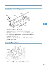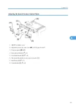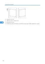
Adjusting the First Scanner Contact Points
1. A(R)DF or platen cover
2. Operation panel, top rear cover ( p.78 "Upper Covers").
3. Exposure glass ( p.85)
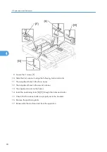
4. Loosen the 2 screws [A] [F].
5. Slide the 1st and 2nd scanners, or one of them, to align the following holes and marks
6. The adjustment holes in the first scanner
7. The adjustment holes in the second scanner
8. The alignment marks on the frames
9. Insert the positioning tools [D] [E] through the holes and marks.
10. Check that the scanner belts [B] [C] [G] [H] are properly set between the bracket and the 1st scanner.
11. Tighten the screws [A] [F].
12. Remove the positioning tools.
13. Reassemble the machine and check the operation.
4. Replacement and Adjustment
92
4
Summary of Contents for Aficio MP 1600L2
Page 1: ...Model K C3 5L Machine Code B244 B276 B277 B268 B269 Field Service Manual 3 December 2010 ...
Page 2: ......
Page 12: ...10 ...
Page 14: ...Machine Configuration 1 Product Information 12 1 ...
Page 20: ...1 Product Information 18 1 ...
Page 70: ...2 Installation 68 2 ...
Page 71: ...3 Preventive Maintenance PM Tables See Appendices for the PM Tables 69 3 ...
Page 74: ...7 Wait until the message Completed shows 8 Quit the SP mode 3 Preventive Maintenance 72 3 ...
Page 139: ...PSU Power Supply Unit 1 Left cover p 79 2 PSU A All connectors x 6 Other Replacements 137 4 ...
Page 151: ...SP Mode Tables See Appendices for the SP Mode Tables SP Mode Tables 149 5 ...
Page 171: ...1 1 0 0 A5 SEF 1 1 1 0 B5 SEF 1 Detected Using SP Modes 169 5 ...
Page 207: ...Model K C3 5L Machine Code B244 B276 B277 B268 B269 Appendices 3 December 2010 ...
Page 208: ......
Page 210: ...2 ...
Page 228: ...2 Appendix Preventive Maintenance 20 2 ...
Page 262: ...MEMO 54 ...
Page 263: ...MEMO 55 ...
Page 264: ...MEMO 56 EN ...


