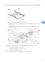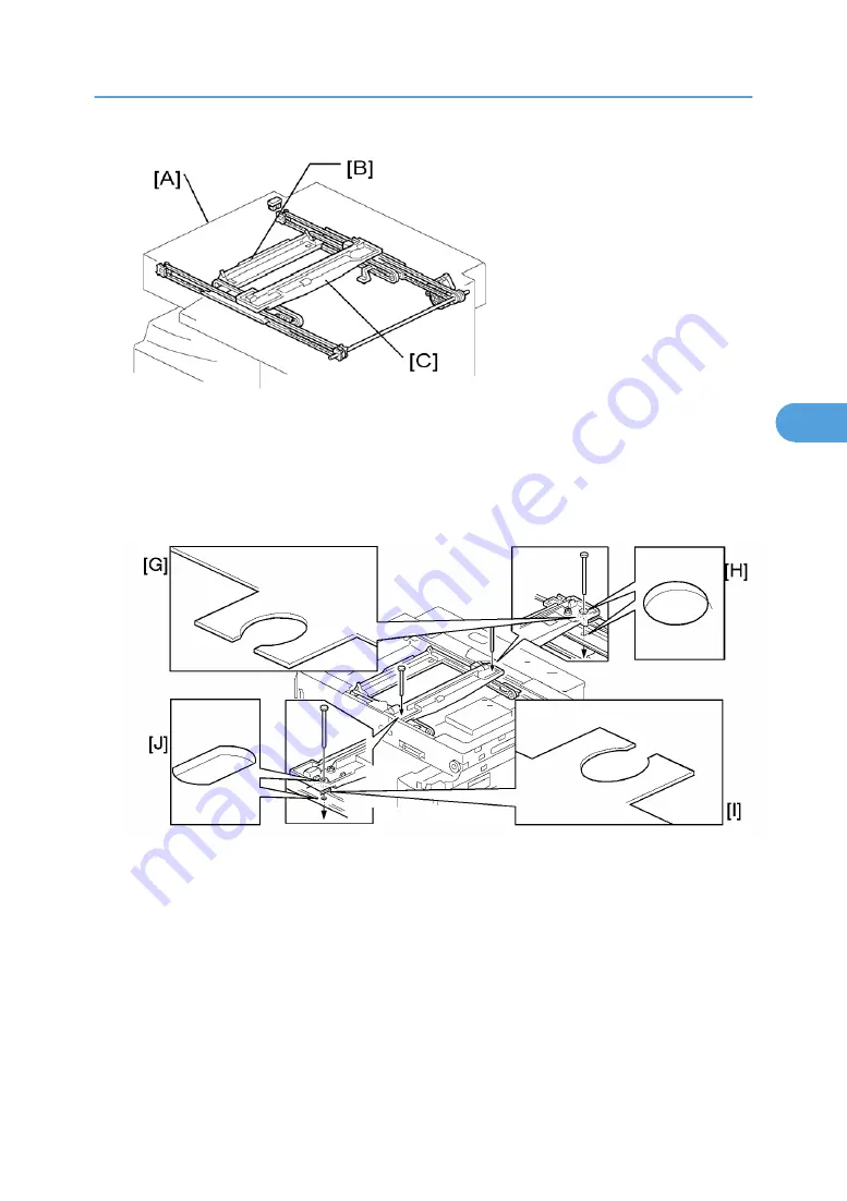
2. To adjust the scanner positions, do either of the following:
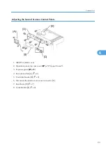
• To adjust the belt contact points on the first scanner (See " Adjusting the First Scanner Contact
Points" below.)
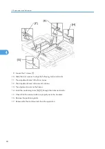
• To adjust the belt contact points on the scanner bracket (See ”Adjusting the Second Scanner
Contact Points" below.)
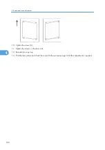
3. The two actions above have the same objectives--to align the following holes and marks:
• The adjustment holes [H] [J] in the first scanner
• The adjustment holes [H] [J] in the second scanner
• The alignment marks [G] [I] on the frames
4. The scanner positions are correct when these holes and marks are aligned.
Scanner Unit
91
4
Summary of Contents for Aficio MP 1600L2
Page 1: ...Model K C3 5L Machine Code B244 B276 B277 B268 B269 Field Service Manual 3 December 2010 ...
Page 2: ......
Page 12: ...10 ...
Page 14: ...Machine Configuration 1 Product Information 12 1 ...
Page 20: ...1 Product Information 18 1 ...
Page 70: ...2 Installation 68 2 ...
Page 71: ...3 Preventive Maintenance PM Tables See Appendices for the PM Tables 69 3 ...
Page 74: ...7 Wait until the message Completed shows 8 Quit the SP mode 3 Preventive Maintenance 72 3 ...
Page 139: ...PSU Power Supply Unit 1 Left cover p 79 2 PSU A All connectors x 6 Other Replacements 137 4 ...
Page 151: ...SP Mode Tables See Appendices for the SP Mode Tables SP Mode Tables 149 5 ...
Page 171: ...1 1 0 0 A5 SEF 1 1 1 0 B5 SEF 1 Detected Using SP Modes 169 5 ...
Page 207: ...Model K C3 5L Machine Code B244 B276 B277 B268 B269 Appendices 3 December 2010 ...
Page 208: ......
Page 210: ...2 ...
Page 228: ...2 Appendix Preventive Maintenance 20 2 ...
Page 262: ...MEMO 54 ...
Page 263: ...MEMO 55 ...
Page 264: ...MEMO 56 EN ...


