


PAPER FEED
SM
6-31
G065
Det
a
iled
De
s
c
ri
ptions
6.9 PAPER
FEED
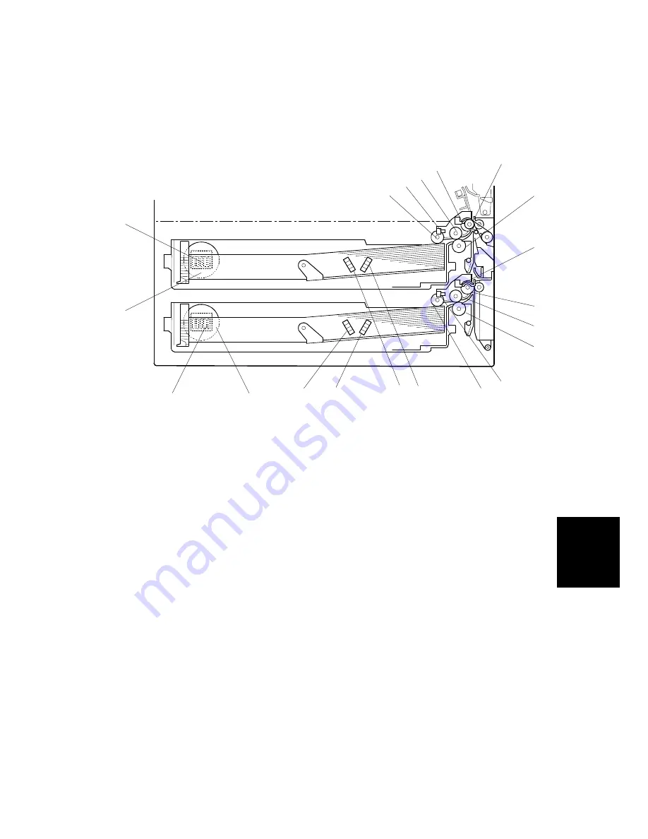
6.9.1 OVERVIEW
1. Upper pick-up roller
2. Upper paper lift sensor
3. Upper paper feed roller
4. Upper relay sensor
5. Upper relay roller
6. Upper separation roller
7. Lower relay sensor
8. Lower relay roller
9. Lower paper feed roller
10. Lower separation roller
11. Lower paper lift sensor
12. Lower pick-up roller
13. Lower paper size dial
14. Lower paper size switch
15. Upper paper size dial
16. Upper paper size switch
17. Upper paper height 2 sensor
18. Upper paper height 1 sensor
19. Lower paper height 2 sensor
20. Lower paper height 1 sensor
Each paper tray, which employs the FRR system, can hold 500 sheets. Two relay
sensors, positioned above each set of relay rollers, detect paper jams. A selection
dial allows you to select the setting for the size of the paper loaded in the tray.
G065D701.WMF
9
13
14
15
16
12
11
10
8
7
6
5
4
3
2
1
20
19
18
17
CÓPIA NÃO CONTROLADA
CÓPIA NÃO CONTROLADA
Summary of Contents for Aficio AP-4510 G065
Page 1: ...G065 SERVICE MANUAL 001269MIU RICOH GROUP COMPANIES C PIA N O CONTROLADA C PIA N O CONTROLADA...
Page 2: ...C PIA N O CONTROLADA C PIA N O CONTROLADA...
Page 3: ...G065 SERVICE MANUAL RICOH GROUP COMPANIES C PIA N O CONTROLADA C PIA N O CONTROLADA...
Page 4: ...C PIA N O CONTROLADA C PIA N O CONTROLADA...
Page 5: ...G065 SERVICE MANUAL 001269MIU C PIA N O CONTROLADA C PIA N O CONTROLADA...
Page 6: ...C PIA N O CONTROLADA C PIA N O CONTROLADA...
Page 8: ...C PIA N O CONTROLADA C PIA N O CONTROLADA...
Page 10: ...C PIA N O CONTROLADA C PIA N O CONTROLADA...
Page 12: ...C PIA N O CONTROLADA C PIA N O CONTROLADA...
Page 20: ...C PIA N O CONTROLADA C PIA N O CONTROLADA...
Page 24: ...C PIA N O CONTROLADA C PIA N O CONTROLADA...
Page 26: ...C PIA N O CONTROLADA C PIA N O CONTROLADA...
Page 27: ...INSTALLATION C PIA N O CONTROLADA C PIA N O CONTROLADA...
Page 28: ...C PIA N O CONTROLADA C PIA N O CONTROLADA...
Page 61: ...PREVENTIVE MAINTANENCE C PIA N O CONTROLADA C PIA N O CONTROLADA...
Page 62: ...C PIA N O CONTROLADA C PIA N O CONTROLADA...
Page 66: ...C PIA N O CONTROLADA C PIA N O CONTROLADA...
Page 67: ...REPLACEMENT AND ADJUSTMENT C PIA N O CONTROLADA C PIA N O CONTROLADA...
Page 68: ...C PIA N O CONTROLADA C PIA N O CONTROLADA...
Page 137: ...TROUBLESHOOTING C PIA N O CONTROLADA C PIA N O CONTROLADA...
Page 138: ...C PIA N O CONTROLADA C PIA N O CONTROLADA...
Page 156: ...C PIA N O CONTROLADA C PIA N O CONTROLADA...
Page 157: ...SERVICE TABLES C PIA N O CONTROLADA C PIA N O CONTROLADA...
Page 158: ...C PIA N O CONTROLADA C PIA N O CONTROLADA...
Page 202: ...C PIA N O CONTROLADA C PIA N O CONTROLADA...
Page 203: ...DETAILED DESCRIPTIONS C PIA N O CONTROLADA C PIA N O CONTROLADA...
Page 204: ...C PIA N O CONTROLADA C PIA N O CONTROLADA...
Page 261: ...BRIDGE UNIT B397 C PIA N O CONTROLADA C PIA N O CONTROLADA...
Page 262: ...C PIA N O CONTROLADA C PIA N O CONTROLADA...
Page 269: ...SPECIFICATIONS C PIA N O CONTROLADA C PIA N O CONTROLADA...