F)
If level of grain inside bag goes too high the roller must be slowed down
to allow more grain to
be removed by the sweeper and discharge augers.
Grain picked up and rolled as one with the plastic
sheet is the telltale sign that should be watched out for.
The roller extremes where the plastic folds
converge on the centering discs is where grain is more likely to collect. If grain is being picked up then
roller speed has to be reduced. If the roller picks up too much grain resulting in prominent and growing
bulges under the plastic, it will be necessary to stop operation, cut the bag, remove plastic sheet from
roller, and reinitiate operation.
G)
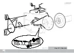
If grain height reaches point “A”, where a substantial amount of grain is being unloaded with none
being picked up by the roller, then roller speed should be stabilized there
. Usually point “A” is the highest
point that the grain can reach without being pulled in with the plastic folds, but the actual clearance to the
roller measured in centimeters can vary. When this plateau is reached, the roller is turning at the correct
speed.
H)
This is the point of equilibrium where inflow and outflow of grain are equal. The amount of grain
that can be handled has reached its peak.
Increasing discharge speed should not be attempted at this
stage
since no benefit in terms of time or volume will be obtained and failure of mechanical parts is a
possibility.
I)
If in doubt, first always try working slower before increasing speed in a gradual manner.
E)
Grain will start coming out of the discharge auger and simultaneously it will start building up inside
the bag to form shape “B” with a certain gradient “D”. The operator should allow a buildup of grain that
will probably take a few minutes to reach point “A”.
D)
Once the bag has been hooked to the roller and the augers are moving, the operator should begin
to haul in the bag by gradually turning open the hydraulic flow control valve (with the roller control lever in
its upper position).
30
Summary of Contents for EA 910
Page 1: ...CDDF00051A RICHIGER EA 910 UNLOADER Parts list Operator s Manual ...
Page 3: ......
Page 10: ...02 Dimensions in millimeters Work position Transport position 9 03 5200 2500 6705 ...
Page 30: ...14 Lubrication chart 9 23 18 15 16 18 19 19 ...
Page 31: ...Lubrication chart 24 17 20 21 22 17 23 ...
Page 41: ...Notes 34 ...
Page 43: ...Sheet N 1 PTO driveline wheels EA 910 36 ...
Page 45: ...EA 350 EA 910 Sheet N 2 Frame 38 EA 910 ...
Page 47: ...30 26 27 28 29 26 27 31 EA 910 Sheet Nº 3 Front end driveline main drive shaft 40 ...
Page 57: ...30 31 Sheet Nº 8 Discharge auger upper section EA 910 50 ...
Page 61: ...Sheet Nº 10 Rear end driveline EA 910 54 ...
Page 63: ...Sheet Nº 11 Gear case EA 910 56 ...
Page 68: ...61 ...
Page 70: ...Sheet Nº 13 Sweep augers EA 910 62 ...
Page 71: ...Sheet Nº 14 Hydraulic controls EA 910 64 16 15 ...
Page 73: ...Sheet Nº 15 Hydraulic circuit EA 910 66 ...
Page 75: ...Notes 68 ...
Page 76: ......


