background image

1
2
3
4

5

6

7

8

9

10
11

12

11

33

16

17

13

14

15

18

19

20

21

22

19

23

19 21 21 32 31

28
29

30

27

26

25

24

19

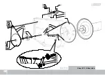
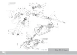
Sheet Nº 5 - Roller drive

 EA 910

44

Summary of Contents for EA 910

Page 1: ...CDDF00051A RICHIGER EA 910 UNLOADER Parts list Operator s Manual ...

Page 2: ...nt manuals updates Therefore contents of this manual are based on development in effect at the time of publication and are subject to change without notice Important Before attempting machine operation read this manual s instructions carefully This manual contains information and recommendations that may vary in accordance with user experience climate grain type tractor weight and other variable c...

Page 3: ......

Page 4: ...thout prior authorization from RICHIGER MAQUINARIAS S A Buyers and their agents shall prepay all transportation charges for the return of such products to RICHIGER MAQUINARIAS S A or designated service center There will be no acceptance of any charges for labor and or parts incidental to the removal and remounting of product repaired or replaced under this warranty This warranty does not cover con...

Page 5: ... to be exhaustive 1 Product suffered damages attributable to accident abuse neglect or ignorance 2 Product was not used in accordance with manufacturer s recommendations 3 Product did not receive required maintenance 4 Failure ensued after replacement of original parts without express consent of RICHIGER MAQUINARIAS S A or modifications that in RICHIGER MAQUINARIAS S A s judgment may have affected...

Page 6: ...urchase Date of Delivery Customer Name Address City State Dealer Name Address City State The machine detailed above and the Operator s Manual have been received and I understand and have been thoroughly instructed by my dealer about how to operate the machine Operator s Manual content equipment care safe operation warranty terms and have personally reviewed the Warranty Policy Terms Buyer s signat...

Page 7: ...Avellaneda 661 S2322BCM Sunchales Province of Santa Fe Argentina Cut Out Warranty Registration Card This form must be filled out and signed by the customer at the time of delivery and sent to factory within 30 days of delivery ...

Page 8: ...mensions 03 page 04 Safety precautions 04 page 05 A word about the hydraulic controls 05 page 06 Switching from transport to work 06 page 09 Attaching the bag 07 page 13 Grain extraction procedure 08 page 16 Ending grain extraction 09 page 16 Emptying the last section of bag 10 page 19 Detaching bag from roller page 20 11 Back to transport position page 21 12 Maintenance 13 page 22 Gear oil fillin...

Page 9: ... bolt protection PowerTransmission Mechanical central discharge auger cross augers Tires 11 L15 10 ply Extraction system Automatic bag pickup system Working height hydraulically controlled Bag slasher blade Works mechanically and hydraulically Adjustable working width Tire pressure 30 lbs sq in Total weight 2000 kg 4400 lbs Work capacity can vary according to grain type moisture content and other ...

Page 10: ...02 Dimensions in millimeters Work position Transport position 9 03 5200 2500 6705 ...

Page 11: ... tow bar pin is properly secured b Check tire pressure c Check that wheel bolts are properly tightened d Attach safety chains between machine s tow bar and tractor drawbar for added security on the road Most accidents are caused by human error Follow all safety procedures Make sure all people are safely positioned before starting tractor s engine and engaging the PTO Keep unloader clean and shelte...

Page 12: ...iclockwise in combination with each specific lever will have on the different hydraulic circuits For example setting roller speed on initiating extraction is simpler if starting from low revs and then increasing them as necessary In this case the knob can initially be turned completely clockwise in which position the roller will not move at all and then progressively be turned counterclockwise unt...

Page 13: ...unction First step in preparing for work is raising the discharge auger With the tractor s hydraulics turned on move first lever A its upward position Fig 2 This will raise the auger tube As soon as auger is fully extended move back the lever to its mid neutral position Once the unloader has finished working and is to be towed away the sequence is reversed and the tube is lowered by moving down th...

Page 14: ...ded Once a combination of stops or a single stop have been selected and placed around the cylinder rod second lever B is pulled down Fig 3 so that the weight of the unloader comes to rest upon the stops Fig 4 At this point the lever is returned to its neutral position The height of the machine can be modified at any point even when the sweep augers are inside the bag IMPORTANT The unloader should ...

Page 15: ...ing the stand upward and attach temporarily to main beam with same pin Fig 5 4 The third lever used to control roller rotation is not used at this stage 6 Pull back the spring loaded pin that holds the roller assembly in place during transport and swivel it 90º to work position Figs 6 7 Fig 5 Fig 7 Fig 8 Fig 6 08 ...

Page 16: ... from their transport location and insert them in the main auger shafts not mixing left and right hand screws Also remove protection grids and install Figs 9 10 9 The sequence is reversed when changing back to transport mode Fig 10 Fig 12 Fig 9 Fig 11 CAUTION Do not prolong the cut to the point where grain is filling the bag and exerting pressure This could cause a rip that spreads along the full ...

Page 17: ...nd so that its cutting edge faces outward The blade will cut open the bag as the roller pulls it in Fig 13 3 Drive the tractor unloader pair in reverse and align with the bag opening as straight and dead center as possible Back up the unloader into the bag until the sweep augers come lightly in contact with the grain but do not shove or attempt to wedge the sweep augers forcefully into the mass of...

Page 18: ...ngth of the roller and that it is the black inner layer of plastic that is visible Punch the plastic sheet through each holding stud Fig 17 leaving a remainder of 10 or 20 inches to the edge Do not worry if the plastic is not perfectly distributed along the length of the roller or if folds and creases remain after attachment Fig 18 Fig 17 Fig 18 9 11 ...

Page 19: ...l be continued by the cutter blade Once unloading operation is underway the initial cut will be continued by the cutter blade Fig 19 Fig 20 IMPORTANT There is no need to be overly precise when fastening the bag to the roller Even though at this stage the plastic may look crumpled and in disarray it will stretch and straighten after a few turns of the roller The basic consideration here is having t...

Page 20: ... be brought to a complete halt by closing the valve knob Open the valve if it was previously closed and augment speed so that grain begins to be delivered through the discharge auger and to accumulate at the front end of the bag 1 Make absolutely sure that the tractor s gear case is disengaged and brakes are off Failure to comply with this can result in a torn bag or mechanical malfunction The mac...

Page 21: ... roller The knob is turned very gradually avoiding any abrupt changes of grain flow The unloader should now be delivering a steady stream of grain to the receiving truck or trailer Fig 25 The truck will have to move every so often to stay alongside the retreating bag Fig 25 CAUTION It is critical that grain not be allowed to collect higher up in the bag than level recommended see General indicatio...

Page 22: ...can curve and the curvature can be quite sudden and pronounced The operator should watch for this while unloading and try to follow curvature with the tractor s steering wheel as far as possible to avoid contact of the augers with the bag s walls CAUTION When not possible to correct misalignment by steering action only in situations as described above operation should be halted and the unloader re...

Page 23: ...tationary The tractor can engage in some gentle forward and reverse action to boost grain collection Repeating this sweeping action the volume to be loaded by hand can be considerably reduced IMPORTANT Whenever grain extraction is ended either if the unloader will remain with bag attached to continue work later or if it will be towed away the correct termination sequence is as follows a The roller...

Page 24: ...he slot located at the base of the discharge auger At this stage the sliding panel or divider that separates the sweep augers from the discharge auger is introduced in corresponding space between auger flightings Fig 29 Then provided crescent shaped covers are attached to the ends of the divider thus effectively covering and sealing both openings of the cylinder shaped grain reception chamber Fig ...

Page 25: ... is shoveled into the auxiliary auger by hand Fig 31 Once unloading is concluded and engine turned off the sweep auger coupling gears handle should be pushed in and the lock pin reinserted The coupling gears are connected to the drive shaft by means of a flange fitted with shear bolts Should these bolts be cut unscrew gear case cover and replace with low carbon steel SAE 1010 or C10 bolts of same ...

Page 26: ...o detach the bag the roller must turn freely The EA 910 model uses an automatic clutch to connect and disconnect the roller drive so there is no need at any time to open the transmission s cover to perform this operation The photo that depicts the operating mechanism is only for information purposes Never operate the machine with protection cover open Detaching bag from roller Fig 32 IMPORTANT Pla...

Page 27: ...es and remove PTO drive shaft d After lifting up the pivoting support stand swivel roller cross beam of a circle into its transport position Then remember to secure support stand to its base once again e Turn cutter blade round so cutting edge faces inward f Remove outer sweeper screws and grids so machine does not exceed road transport width allowance g Hitch unloader to towing vehicle Fig 37 Fig...

Page 28: ...er s driveline and transmission from overloads Should they have to be replaced use soft low carbon steel SAE 1010 or C10 bolts of same diameter as the original Never use hardened steel bolts or pins as replacements Shear bolts Lubrication Roller gearbox sweep auger and discharge auger transmission cases and chains Use SAE 140 gear oil Bearings and chains Use heavy duty lithium grease Never perform...

Page 29: ...ional liters Oil passage is slow especially in low temperatures and this is the reason why two filling steps are required It helps if oil is warmed slightly Before replacing the fill plug turn transmission on Any oil quantity in excess will be thrust out through the plug opening Peering down oil should be visible at about mid level to ensure proper gear lubrication If oil surface is not visible po...

Page 30: ...14 Lubrication chart 9 23 18 15 16 18 19 19 ...

Page 31: ...Lubrication chart 24 17 20 21 22 17 23 ...

Page 32: ... drive Chain tensioner 2 Grease 50 12 Auger drive chain Apply w brush Grease 50 13 Roller drive Chain tensioner 1 Grease 50 14 Roller drive chain Apply w brush Grease 50 15 Tri lobed plates 2 Grease 50 16 Front drive Front drive chain Apply w brush Grease 50 17 Rear drive Rear drive chain Apply w brush Grease 50 18 Wheel spindles Bearing caps 3 Grease 50 19 Roller Roller bearings 2 Grease 50 20 Ja...

Page 33: ...f grain Corn above 22 moisture Soybeans above 22 moisture Wheat above 20 moisture Sunflower Oats Barley Paddy rice Chickpeas Grains that flow with more difficulty should be extracted at a slower pace as the higher speeds cannot be attained and if attempted the unloader could suffer mechanical damage Examples of these grains are Corn below 21 moisture Soybeans below 21 moisture Wheat below 19 moist...

Page 34: ...ape lends itself to interlocking In these less than ideal conditions work speed is necessarily compromised The following drawings depict magnitudes A B C D The text that follows can help you assess how these parameters interact with each other and with different grains to help optimize operation A is the height that grain within the bag can be taken to by increasing or reducing the pickup roller s...

Page 35: ...ers and bag bottom or ground This distance should be small so that the sweep augers lie low inside the bag and are well covered with grain which ensures adequate delivery to the discharge auger The clearance is set via clamp stops placed on the hydraulic cylinder rod Since the augers should not touch the ground as this would endanger bag integrity the convenience of placing the bags on terrain as ...

Page 36: ...unit of time compared with free flowing material A First adjust C so that sweeper distance to the ground is the minimum possible This allows the augers to tackle the mass of grain from a lower point so that more grain can accumulate above them and form a steeper angle D This will cause the wall of grain to tumble down more readily and better feed the augers Remember that minimum is a relative term...

Page 37: ...without being pulled in with the plastic folds but the actual clearance to the roller measured in centimeters can vary When this plateau is reached the roller is turning at the correct speed H This is the point of equilibrium where inflow and outflow of grain are equal The amount of grain that can be handled has reached its peak Increasing discharge speed should not be attempted at this stage sinc...

Page 38: ...ed for elevation or rotation do not perform maintenance work without ensuring that a Engine is off b Nobody has ignition keys to inadvertently turn engine on c Safety stops are in place d There are supporting stands between machine and ground 12 Ensure that operator is familiar with fire hazard procedures and proficient with a fire extinguisher Following all safety routines involves a high degree ...

Page 39: ...r forearm back and forth Fig 4 MOVE OUT TAKE OFF Face desired direction of movement Extend arm straight out behind you then swing it overhead and forward until it s straight out in front of you Fig 5 STOP Raise arm straight up palm to the front 19 Hand signals Hand signals have been developed to provide a uniform means of communication between workers on the ground and equipment operators They are...

Page 40: ...ur right arm across your neck from left to right in a throat cutting motion Fig 6 SPEED IT UP Clenching your fist bend your arm so your hand is at shoulder level Thrust arm rapidly straight up and down several times Fig 10 LOWER EQUIPMENT Point toward the ground with the forefinger of one hand while moving the hand in a circle Fig 11 RAISE EQUIPMENT Point upward with forefinger while making a circ...

Page 41: ...Notes 34 ...

Page 42: ...eet Nº 7 Pivoting beam roller assy Sheet Nº 8 Discharge auger upper section Sheet Nº 9 Discharge auger lower section Sheet Nº 10 Rear end driveline Sheet Nº 11 Gear case Sheet Nº 12 Sweep auger drive Sheet Nº 13 Sweep augers Sheet Nº 14 Hydraulic controls Sheet Nº 15 Hydraulic circuit page 36 page 38 page 40 page 42 page 44 page 46 page 48 page 50 page 52 page 54 page 56 page 58 page 62 page 64 pa...

Page 43: ...Sheet N 1 PTO driveline wheels EA 910 36 ...

Page 44: ...009 2RS MCRO00001 2 19 Drive shaft short CDBW00174 1 20 Drive shaft housing CDBV00025 1 EA 910 Sheet N 1 PTO driveline wheels Nº Description Code Qty 21 Bearing cap wheel axle CDBZ50071 3 22 Flat washer 3 16 OD 35 ID 20 mm CDAA42008 6 23 Disc springs 3 4 40x20 4x2 25 mm MCAR01001 6 24 Hex bolt gr 5 NF 3 4 x5 MCBU02039 6 25 Oil seal 48x82x8 mm MCRE00036 2 26 Bearing 30208 MCRO06006 2 27 Bearing cap...

Page 45: ...EA 350 EA 910 Sheet N 2 Frame 38 EA 910 ...

Page 46: ...2 4 14 R clip w ring MCCH03001 4 15 Support bracket grid extension CDBW00260 4 16 Hex bolt gr 5 BSW 1 2 x1 MCBU00024 4 17 Support bracket discharge auger CDBW50069 1 18 Supporting pillar roller assy CDBW50070 1 19 Snap ring 35A DIN471 MCSE01010 1 20 Cover plate frame beam CDBW00228 2 21 Lock pin roller support pillar CDBW50057 1 22 Auxiliary bin CDBW00137 1 23 Wing bolt 3 8 CDBE50011 1 24 User s m...

Page 47: ...30 26 27 28 29 26 27 31 EA 910 Sheet Nº 3 Front end driveline main drive shaft 40 ...

Page 48: ...Idler arm front CDBW50048 1 13 Flat washer galvanized 1 2 MCAR00007 1 14 Hex nut gr 5 BSW 1 2 MCTU00005 1 15 Idler sprocket 12 tooth f ASA 80 1 chain CDBW00006 1 16 Bearing 6205 2RS MCRO00017 1 17 Snap ring 52I DIN472 MCSE00004 1 18 Snap ring 25A DIN471 MCSE01006 1 19 Sprocket 17 tooth f ASA 80 1 chain CDBW00005 2 20 Disc springs 3 8 20x10 2x0 8 mm MCAR01006 4 21 Flat washer galvanized 3 8 MCAR000...

Page 49: ...1 2 3 4 5 6 8 7 9 10 11 10 16 12 11 13 14 13 14 3 15 Sheet Nº 4 Roller coupling mechanism EA 910 42 ...

Page 50: ...ut BSW 3 8 MCTU06001 2 6 Disc springs 3 8 20x10 2x0 8 mm MCAR01006 2 7 Hex bolt gr 5 BSW 3 8 x1 1 4 MCBU00008 2 8 Disengage point indicator CDDF00012 1 9 Sprocket 95 tooth f ASA 60 1 w bronze bushing CDDF50004 1 10 Hex bolt BSW 5 8 x3 1 2 MCBU01084 2 11 Coupling arm CDDF00009 2 12 Bushing CDDF00005 1 13 Flat washer galvanized 5 8 MCAR00009 2 14 Self locking nut BSW 5 8 MCTU06005 2 15 Engaging plat...

Page 51: ...1 2 3 4 5 6 7 8 9 10 11 12 11 33 16 17 13 14 15 18 19 20 21 22 19 23 19 21 21 32 31 28 29 30 27 26 25 24 19 Sheet Nº 5 Roller drive EA 910 44 ...

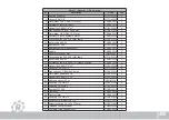
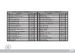
Page 52: ...ey 8x8x40 mm CDBZ00061 1 15 Connecting link ASA 60 1 roller chain MCCA01016 1 16 Roller chain ASA 60 CDDF00039 1 17 Sprocket 95 tooth f ASA 60 1 w bronze bushing CDDF50004 1 18 Hex bolt gr 5 BSW 1 2 x2 MCBU00069 1 19 Hex nut gr 5 BSW 1 2 MCTU00005 4 20 Disc springs 1 2 24x13x2 8 mm MCAR03002 2 21 Flat washer galvanized 1 2 MCAR00007 2 22 Hex bolt gr 5 BSW 1 2 x2 MCBU00028 2 23 Hydraulic motor 250 ...

Page 53: ...2 3 1 5 6 8 4 10 3 9 11 12 17 3 18 22 21 21 20 19 23 22 13 3 2 3 10 16 15 14 25 24 26 28 29 30 31 3 2 33 32 21 27 22 7 10 3 22 Sheet Nº 6 Gear plate covers EA 910 46 ...

Page 54: ...rip CDBF00023 1 15 Acrylic window CDBF00021 1 16 Supplementary back cover CDDF00015 1 17 Hex bolt gr 5 BSW 3 8 x1 MCBU00007 6 18 Gear plate CDDF50006 1 19 Extension spring 2 5 x 19 x 135 mm MCRS00003 1 20 Threaded spring tensioner CDBW50086 1 21 Flat washer galvanized 1 2 MCAR00007 6 22 Hex nut gr 5 BSW 1 2 MCTU00005 7 23 Hex bolt gr 5 BSW 1 2 x2 MCBU00069 1 24 Hex bolt gr 5 BSW 1 2 x2 MCBU00028 2...

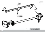
Page 55: ...7 12 15 7 2 3 4 5 1 7 8 9 10 11 6 13 14 16 17 14 Sheet Nº 7 Pivoting beam roller assy EA 910 48 ...

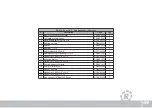
Page 56: ...C 210 MCRO12007 1 7 Self locking nut BSW 5 8 MCTU06005 1 8 Bearing housing for bearing UC 210 CDAA51041 1 9 Hex bolt gr 5 BSW 5 8 x2 1 4 MCBU00038 1 10 Mounting bracket CDDF00014 4 11 Hex bolt gr 5 BSW 5 8 x1 1 2 MCBU00035 1 12 Pivoting beam roller assy CDDF50017 7 13 Pivot pin roller assy CDBW50065 1 14 Washer pivot pin CDBW00192 1 15 Hex bolt gr 5 BSW 5 8 x1 3 4 MCBU00036 7 16 Hex bolt gr 5 BSW ...

Page 57: ...30 31 Sheet Nº 8 Discharge auger upper section EA 910 50 ...

Page 58: ...sion CDBW00213 1 16 Grease zerk straight SAE 1 4 MCAL00002 1 17 Bearing UC 207 2L MCRO12008 1 18 Bearing housing UC 207 CDBW00036 1 19 Flat washer galvanized 1 2 MCAR00007 4 20 Compression spring 3 x 26 x 120 mm MCRS01002 4 21 Hair Pin clip 4 5 x 90 mm MCCH05002 2 22 Clevis pin 25 x 94 5 mm hydraulic cylinder MCHI07142 1 23 Hydraulic cylinder 1 1 4 rod diameter x 2 1 2 sleeve bore x 500 mm stroke ...

Page 59: ...7 4 6 6 13 10 19 12 8 15 5 14 16 11 9 20 21 10 2 17 3 5 22 1 18 Sheet Nº 9 Discharge auger lower section EA 910 52 ...

Page 60: ...arge tube lower section CDBZ50058 1 10 Self locking nut BSW 1 2 MCTU06003 2 11 Support bracket bearing housing CDBW50016 1 12 Hex bolt gr 5 BSW 1 2 x1 1 4 MCBU00003 2 13 Hex nut gr 5 BSW 1 MCTU00010 1 14 Coupling auger lower section CDBW50019 1 15 Bearing UC 208 3L MCRO12010 1 16 Bearing housing UC 208 3L CDAA51036 1 17 Grease zerk 45 angle SAE 1 4 MCAL01001 1 18 Complete UC 208 bearing bracket as...

Page 61: ...Sheet Nº 10 Rear end driveline EA 910 54 ...

Page 62: ... 1 14 Sprocket 22 tooth f ASA 80 1 chain CDBW00007 1 15 Bracket driveshaft casing CDBZ50015 1 16 Flat washer galvanized 1 2 MCAR00007 7 17 Disc springs 1 2 24x13x2 8 mm MCAR03002 11 18 Hex nut gr 5 BSW 1 2 MCTU00005 1 19 Cover plate chain 1 side CDBW00035 1 20 Disc springs 1 4 14x7 2x0 8 mm MCAR01005 16 21 Hex bolt gr 5 BSW 1 4 x5 8 MCBU00004 16 22 Large cover plate discharge tube CDBZ00027 1 23 H...

Page 63: ...Sheet Nº 11 Gear case EA 910 56 ...

Page 64: ... CDBW50078 1 16 Splined shaft chain drive CDBW00095 1 17 Bearing 6208 2RS MCRO00023 1 18 Driven sprocket 18 tooth f ASA 80 1 chain CDBW50079 1 19 Hex nut NF 1 1 8 MCTU02011 2 20 Conical gear 21 tooth CDBW00042 3 21 Housing rear driveline CDBZ50014 1 22 Oil seal 40x80x12 mm MCRE00040 1 23 Bearing housing 30208 CDBW00041 1 24 Drive sprocket 18 tooth f ASA 80 1 chain CDBW00170 1 25 Threaded plug 1 4 ...

Page 65: ... 11 12 13 14 15 16 17 20 18 22 23 25 26 27 19 39 40 29 28 6 31 32 33 34 35 32 36 37 48 41 42 43 45 46 47 21 30 12 49 51 52 50 53 58 57 56 61 59 60 51 55 54 49 12 18 18 63 62 7 62 44 38 24 Sheet Nº 12 Sweep auger drive EA 910 58 ...

Page 66: ...ght SAE 1 4 MCAL00002 3 19 Lock pin sweep augers CDBZ50023 1 20 Bushing lock pin CDBZ00051 1 21 Spring lock pin MCRS01010 1 EA 910 Sheet Nº 12 Sweep auger drive Nº Description Code Qty 22 Bushing small CDBZ00071 1 23 Split pin 2x20 mm MCCH01002 1 24 Complete lock pin assy CDBZ50028 1 25 Flat washer galvanized 5 16 MCAR00004 4 26 Disc springs 5 16 16x8 2x0 6 mm MCAR01004 4 27 Hex bolt gr 5 BSW 5 16...

Page 67: ... bracket oil seal CDBZ00042 1 51 Square head set screw 3 8 x3 4 MCPR00014 2 52 Hex nut gr 5 BSW 3 8 MCTU00003 1 53 Outer ring flange bracket CDBZ00008 1 54 Square key 8x8x65 mm CDBZ00060 1 55 Hex nut gr 5 BSW 1 2 MCTU00005 2 56 Snap ring 62I DIN472 MCSE00003 1 57 Oil seal 35x62x10 mm MCRE00031 1 58 Hex bolt gr 5 BSW 3 8 x3 4 MCBU00005 4 59 Idler arm left side CDBZ50018 1 60 Double gear 22 teeth sw...

Page 68: ...61 ...

Page 69: ...ht end section CDBW50003 1 12 Protection grid right middle section CDBZ50034 1 13 Sweep auger center section CDBZ50012 1 14 Hex bolt BSW 3 8 x 2 1 2 MCBU01034 2 15 Disc springs 3 8 20x10 2x0 8 mm MCAR01006 2 16 Hex nut gr 5 BSW 3 8 MCTU00003 2 17 Sweep auger right end section CDBX50002 1 18 Sweep auger left end section CDBX50003 1 19 Support bracket bearing housing CDBZ50013 1 20 Flat washer galva...

Page 70: ...Sheet Nº 13 Sweep augers EA 910 62 ...

Page 71: ...Sheet Nº 14 Hydraulic controls EA 910 64 16 15 ...

Page 72: ...control valve MCHI06016 1 6 Pressure relief valve MCHI06017 1 7 Spring centered spool 1 position detent MCHI07101 1 8 Closure section MCHI07115 1 9 Central body MCHI06018 1 10 Plug solid MCHI07116 1 11 Spring divider spool MCHI07117 1 12 Replacement plug SVLP MCHI07118 1 13 Lever actuator assy MCHI07119 3 14 Central body MCHI06019 2 15 Cover repair kit MCHI00032 1 16 Body repair kit MCHI00033 4 ...

Page 73: ...Sheet Nº 15 Hydraulic circuit EA 910 66 ...

Page 74: ...Hydraulic hose 1 2 SAE 100R2 AT x 500 mm connectors 7 8 male UNF JIC 37 x 7 8 male UNF w o ring seat MCHI04093 2 12 Sauer Danfoss orbital motor 50 cc displacement MCHI01002 1 13 Hydraulic cylinder 1 1 4 rod diameter x 3 sleeve bore x 8 stroke MCHI02024 1 14 Hydraulic hose 1 4 SAE 100R2 AT x 660 mm connectors 7 8 male UNF w o ring seat x 3 4 male UNF w o ring seat MCHI04019 1 15 Hydraulic hose 1 4 ...

Page 75: ...Notes 68 ...

Page 76: ......

Reviews: