OPERATION
RC115/118/120/125 02/12
Operation Section 4-12
© 2012 Alamo Group Inc.
OPERA
T
ION
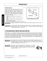
Driveline Clearance
.
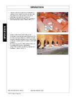
Pull Type Units - After adjusting drawbar to correct
length and attaching mower, check driveline for
telescoping clearance. Before engaging PTO
ensure driveline does not bottom out during sharp
turns. Check vertical clearance between driveline
and hitch pin. Driveline should have a minimum
overlap of 5” at all times.
•
Disengage the driveline from the tractor PTO
shaft.
•
Slide the driveline together until it “bottoms out”
solidly.
•
Apply colored tape to the inner shield 1/8” from
the end of the outer shield.
•
Reattach the driveline to the PTO shaft.
OPS-F-0001_A
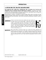
Driveline may bottom out or come in contact with hitch while traveling over uneven terrain.
A loose driveline could slip off and result in personal injury or damage to shredder. When
attaching driveline yoke to tractor PTO shaft, it is important that spring-activated locking
collar be seated in groove on PTO shaft.
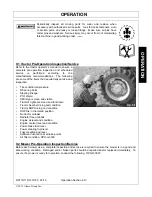
9. PRE-OPERATION INSPECTION AND SERVICE
Before each use, a pre-operation inspection and service of the implement and tractor must be performed.
This includes routine maintenance and scheduled lubrication, inspecting that all safety devices are equipped
and functional, and performing needed repairs. DO NOT operate the unit if the pre-operation inspection
reveals any condition affecting safe operation. Perform repairs and replacement of damaged and missing
parts as soon as noticed. By performing a thorough pre-operation inspection and service, valuable down time
and repair cost can be avoided.
OPS-U-0029
Always disconnect the main PTO Driveline from the Tractor before performing service on
the Implement. Never work on the Implement with the tractor PTO driveline connected and
running. Rotating Parts, Blades or Drivelines could turn without warning and cause
immediate entanglement, injury or death.
(S3PT-11)
Never work under the Implement, the framework, or any lifted
component unless the Implement is securely supported or blocked up
to prevent sudden or inadvertent falling which could cause serious
injury or even death.
(SG-14)
Summary of Contents for RC 115
Page 6: ......
Page 10: ......
Page 11: ...Safety Section 1 1 2012 Alamo Group Inc SAFETY SECTION...
Page 28: ...SAFETY RC115 118 120 125 02 12 Safety Section 1 18 2012 Alamo Group Inc SAFETY...
Page 29: ...SAFETY RC115 118 120 125 02 12 Safety Section 1 19 2012 Alamo Group Inc SAFETY...
Page 30: ...SAFETY RC115 118 120 125 02 12 Safety Section 1 20 2012 Alamo Group Inc SAFETY...
Page 31: ...SAFETY RC115 118 120 125 02 12 Safety Section 1 21 2012 Alamo Group Inc SAFETY...
Page 32: ...SAFETY RC115 118 120 125 02 12 Safety Section 1 22 2012 Alamo Group Inc SAFETY...
Page 33: ...SAFETY RC115 118 120 125 02 12 Safety Section 1 23 2012 Alamo Group Inc SAFETY...
Page 34: ...SAFETY RC115 118 120 125 02 12 Safety Section 1 24 2012 Alamo Group Inc SAFETY...
Page 36: ......
Page 37: ...Introduction Section 2 1 2012 Alamo Group Inc INTRODUCTION SECTION...
Page 42: ......
Page 43: ...Assembly Section 3 1 2012 Alamo Group Inc ASSEMBLY SECTION...
Page 48: ......
Page 49: ...Operation Section 4 1 2012 Alamo Group Inc OPERATION SECTION...
Page 88: ......
Page 89: ...Maintenance Section 5 1 2012 Alamo Group Inc MAINTENANCE SECTION...
Page 108: ...MAINTENANCE RC115 118 120 125 02 12 Maintenance Section 5 20 2012 Alamo Group Inc MAINTENANCE...
Page 109: ......
Page 122: ...Secci n de Seguridad 1 1 2012 Alamo Group Inc SECCI N DE SEGURIDAD...
Page 123: ......


