25
SSCBL-RPBL-IOM (10-22) 149159-C
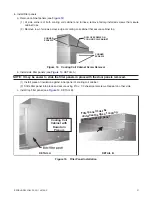
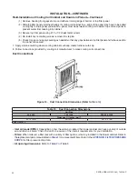
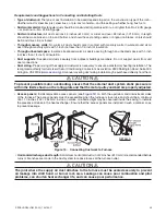
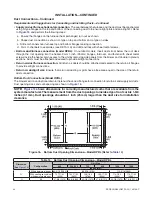
100% Outside Air Hood (Model RPBL with Option AS2)
⚠ CAUTION ⚠
It is recommended that the inlet to the outside air hood NOT be facing into the prevailing wind.
Allow a minimum clearance of 14 inches (356 mm) from the bottom of the air hood to the mounting
surface.
Option AS2 is a weatherized, screened hood designed to be field-assembled and installed around the horizontal
inlet air opening of the blower cabinet . The air hood includes factory-assembled louvers designed to help eliminate
moisture from the inlet air . Complete installation instructions are packaged with the air hood and are listed in
Screened Air Hood for 30% Outside Air Opening (Model RPBL with Option AR6 or AR7)
The outside air hood included in the air inlet options that have a 30% outside air opening (options AR6 and AR7) is
shipped separately for field-installation . Complete installation instructions are packaged with the air hood and are
listed in
Evaporative Cooling Module (Option AS3, AS4, AS5, or AS8)
The evaporative cooling module is factory-assembled, installed and wired . No additional roof mounting is necessary .
Refer to the installation manual listed in
to field-connect the water supply and to make necessary checks
and adjustments before operating the cooling module .
Discharge Air Temperature Sensor Installation
1 . Determine distance of sensor from unit:
a . Ensure that there is sufficient distance from outlet to have good mixture of discharge air temperature .
NOTES:
• According to the latest edition of AMCA Standard 201, in straight ducts, the air is typically well
mixed a minimum of five equivalent duct diameters from the discharge of the unit with equivalent
duct diameter defined as equal to the square root of 4AB/3.14 (A and B are duct cross-sectional
dimensions).
• Locate the sensor a minimum of 96 inches (2,435 mm) from the outlet of the unit.
• If the length of the discharge duct is less than 8 feet (2.4 meters), a mixing vane is recommended
for mixing the discharge air. Do not mount the sensor in the ductwork after a split in the supply
as this will cause loss of control in the duct that does not house the sensor.
b . Refer to following formula for calculating sensor placement . This example assumes cross-sectional dimensions
for supply ductwork of 24
×
12 inches (610
×
305 mm):
5
𝑒𝑒𝑒𝑒𝑒𝑒𝑒𝑒𝑒𝑒𝑒𝑒𝑒𝑒𝑒𝑒𝑒𝑒𝑒𝑒𝑒𝑒𝑒𝑒𝑒𝑒𝑒𝑒𝑒𝑒𝑒𝑒𝑒𝑒𝑒𝑒𝑒𝑒𝑒𝑒
𝑑𝑑𝑑𝑑𝑒𝑒𝑒𝑒𝑑𝑑𝑑𝑑𝑒𝑒𝑒𝑒
𝑑𝑑𝑑𝑑𝑒𝑒𝑒𝑒𝑒𝑒𝑒𝑒𝑑𝑑𝑑𝑑𝑒𝑒𝑒𝑒𝑒𝑒𝑒𝑒𝑒𝑒𝑒𝑒𝑑𝑑𝑑𝑑𝑑𝑑𝑑𝑑
×
�
4 × 12 × 24
3.14
= 96
𝑒𝑒𝑒𝑒𝑒𝑒𝑒𝑒𝑑𝑑𝑑𝑑ℎ𝑒𝑒𝑒𝑒𝑑𝑑𝑑𝑑
5
𝑒𝑒𝑒𝑒𝑒𝑒𝑒𝑒𝑒𝑒𝑒𝑒𝑒𝑒𝑒𝑒𝑒𝑒𝑒𝑒𝑒𝑒𝑒𝑒𝑒𝑒𝑒𝑒𝑒𝑒𝑒𝑒𝑒𝑒𝑒𝑒𝑒𝑒𝑒𝑒
𝑑𝑑𝑑𝑑𝑒𝑒𝑒𝑒𝑑𝑑𝑑𝑑𝑒𝑒𝑒𝑒
𝑑𝑑𝑑𝑑𝑒𝑒𝑒𝑒𝑒𝑒𝑒𝑒𝑑𝑑𝑑𝑑𝑒𝑒𝑒𝑒𝑒𝑒𝑒𝑒𝑒𝑒𝑒𝑒𝑑𝑑𝑑𝑑𝑑𝑑𝑑𝑑
×
�
4 × 305 × 610
3.14
= 2435
𝑑𝑑𝑑𝑑𝑒𝑒𝑒𝑒𝑒𝑒𝑒𝑒𝑒𝑒𝑒𝑒𝑒𝑒𝑒𝑒𝑑𝑑𝑑𝑑𝑒𝑒𝑒𝑒𝑒𝑒𝑒𝑒𝑒𝑒𝑒𝑒𝑑𝑑𝑑𝑑𝑑𝑑𝑑𝑑
2 . Determine orientation of sensor:
a . In horizontal ductwork, position sensor in top-middle of duct with sensor probe extending vertically down into
center of air stream .
b . In vertical ductwork, position sensor in middle of duct that corresponds with top-middle of discharge outlet .


