47
SSCBL-RPBL-IOM (10-22) 149159-C
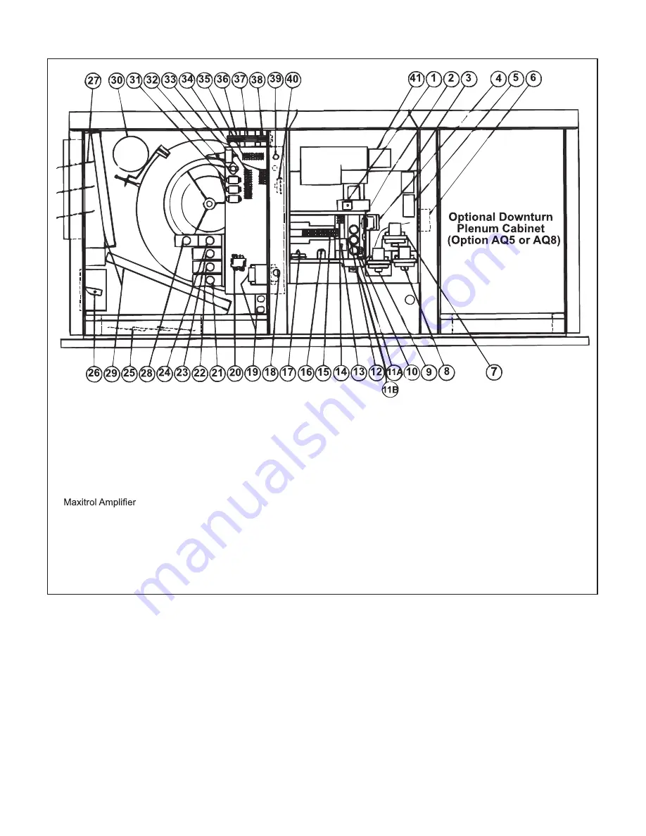
Figure 36. Typical Control Locations
1) Auto-Reset Freezestat
2) Combustion Air Pressure
Switch
3) Discharge Air Firestat
4) Ignition Controller
5) Maxitrol Discharge Air
Sensor
6) Two-Stage Controller or
7) Main Low Gas Pressure
Switch
8) Pilot High Gas Pressure
Switch
9) Main High Gas Pressure
Switch
10) Time Delay Relay
11A) Limit Control (Disc Type)
11B) Limit Control (Capillary
Type)
12) Fan Control
13) Freezestat Time Delay
Relay
14) Line Voltage Terminal
Block
15) Low Voltage Terminal
Block
16) Freezestat Relay
17) Dirty Filter Pressure
Switch
18) Line Voltage Connection
19) Convenience Outlet and
Outlet Transformer
20) Blower Motor Contactor or
Starter
21) High Ambient Limit
Control and/or Heat Stage
Controls (2 or 4)
22) Outside Air or Return Air
Controller
23) Mixed Air Controller
24) Potentiometer
25) Return Air Dampers
26) Two-Position or
Modulating Damper Motor
27) Outside Air Damper
28) Potentiometer
29) Filters
30) Blower Motor
31) Control Relays
32) Auto-Reset Reverse Flow
Limit
33) Return Air Firestat
34) Low Voltage Terminal
Strip
35) Line Voltage Terminal
Strip
36) Control Transformer
37) Control Transformer
38) Damper Motor
Transformer
39) Low Voltage Connection
40) Air Proving Switch
41) Venter Assembly


