46
SSCBL-RPBL-IOM (10-22) 149159-C
INSTALLATION—CONTINUED
Electrical Connections—Continued
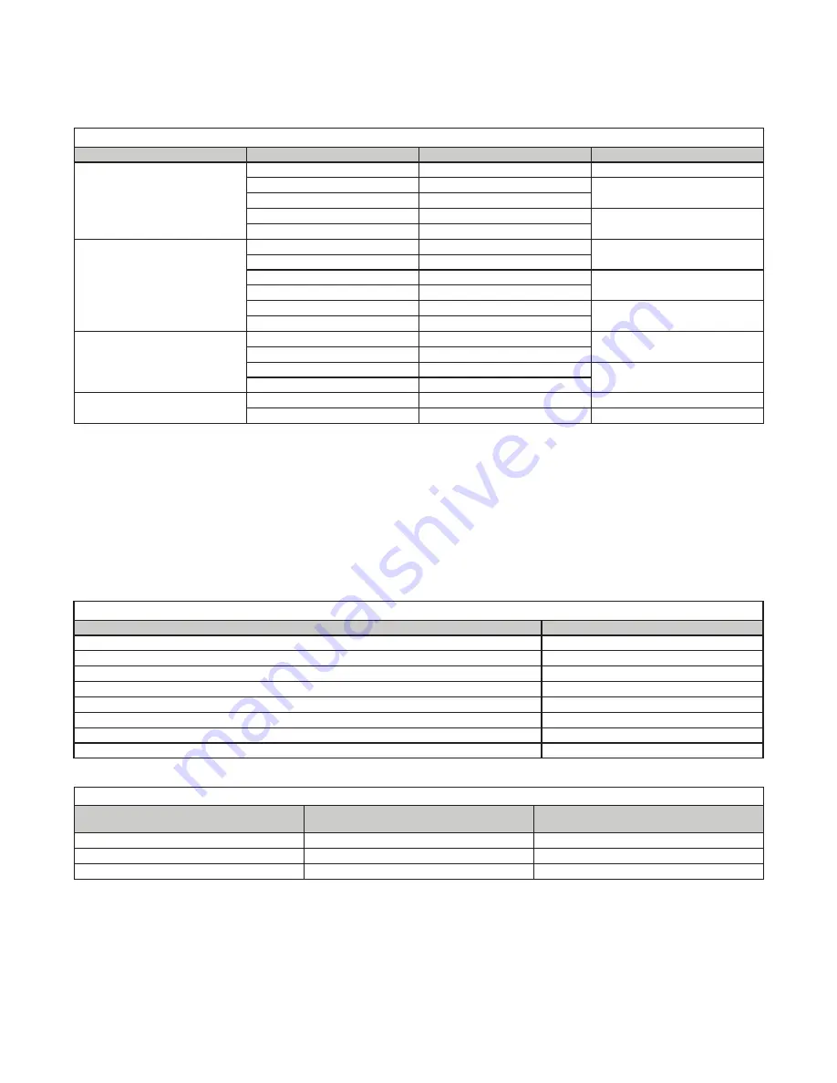
Table 23. Field-Supplied Wiring Sizes
Voltage/Phase
Motor HP
Wire Gauge
BX Cable Size (Inches)
208/1, 230/1
1–2
14
3/8
3
10
1/2
5
8
7 .5
6
1
10
4
208/3, 230/3
1–3
14
3/8
5
12
7 .5
10
1/2
10
8
15
6
1
20
4
460/3
1–7 .5
14
3/8
10
12
15
10
1/2
20
8
575/3
1–7 .5
14
3/8
10–20
10
1/2
Control Wiring
•
for amp ratings of optional controls . Refer to
for the recommended maximum length
and minimum gauge of control wiring .
•
There are a variety of optional controls (see
) available as part of the gas and air control options . Optional
shipped-separate heating and makeup air controls could include a single or two-stage thermostat, system switches,
Selectrastat, freezestat, discharge temperature low limit, an automatic night setback device, a Maxitrol temperature
selector, a potentiometer, a pressure null switch, or a combination of these controls . Install controls according to
the manufacturer’s instructions packaged with the heater .
Table 24. Amp Ratings of 24V Optional Controls
Control
Ampere Rating (Maximum Amps)
Fan control
0 .12
Heater
0 .14
RBM relay coil
2 .00
Contactor coil
0 .45
Spark ignition system
0 .10
Maxitrol gas control system
0 .51
Single-stage gas valve
0 .60
Two-stage gas valve
0 .60
Table 25. Control Wiring Sizes
Distance from Unit to Control
(Feet (Meters))
Minimum Recommended Wire Gauge
(AWG)
Total Wire Length
(Feet (Meters))
75 (23)
#18
150 (46)
125 (38)
#16
250 (76)
175 (53)
#14
350 (107)


