53
SSCBL-RPBL-IOM (10-22) 149159-C
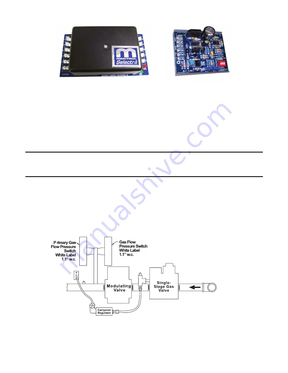
AMPLIFIER
SIGNAL CONDITIONER
Figure 38. Maxitrol Amplifier and Signal Conditioner
Computer-Controlled Electronic Modulation Between 50% and 100% Firing Rate (Option AG21)
•
With option AG21, the furnace is equipped with a Maxitrol signal conditioner (see
the same way as the amplifier above to control the regulator valve . The signal conditioner accepts an input signal
of either 4–20 milliamps or 0–10V from a customer-supplied control device such as a computer .
•
With the dip switches on the conditioner positioned to ON, the conditioner accepts a 4–20 milliamp signal . With
the dip switches on the conditioner positioned to OFF, the conditioner accepts a 0–10V signal . The conditioner
converts the signal to the 0–20V DC current required to control the modulating valve .
Electronic Modulation Between 25% and 100% Firing Rate (Options AG39, AG40, AG41, and AG42)
NOTE: Options AG39, AG40, AG41, and AG42 are available only with natural gas. A unit size 400
equipped with electronic modulation option AG39 has a 25–100% firing range (4:1 turndown ratio).
Option AG41 applies to unit sizes 500, 600, and 800 with two furnaces and to unit size 1200 with
three furnaces.
•
The furnace closest to the blower is equipped with the electronic modulation option . The other furnace(s) have
two-stage burner control from outside air temperature sensors identified as heat stage controllers . Option AG41
provides 6:1 turndown with two furnaces and 8:1 turndown with three furnaces .
•
The furnace will ignite at any input rate in the available range and will maintain average thermal efficiencies equal
to or greater than the thermal efficiency at full fire .
•
) includes a single-stage gas valve, a modulating valve, and two gas pressure switches .
The burner rack is equipped with one flash carryover and a regulated gas lighter tube system . The carryover lighter
tube receives its gas supply through the regulator simultaneously with the gas to the burner . Control of the system
is through a Maxitrol amplifier (see
) with a corresponding remote temperature dial .
Note: Arrangement may vary slightly depending on
gas valve; components are the same.
Figure 39. Typical Manifold Arrangement with Electronic Modulation


