background image

8

SSCBL-RPBL-IOM (10-22) 149159-C

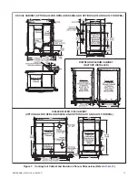
Package Configurations

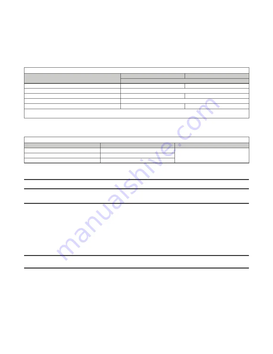
Table 6.  Package Configurations

Unit Size

No. of Furnace Sections

No. of Blower Cabinets

400

1

1

500, 600, 700, 800

2

1050, 1200

3

GENERAL INFORMATION—CONTINUED

Clearances

Clearance to combustibles is defined as the minimum distance—from the heater to a surface or object—that is 

necessary to ensure that a surface temperature of 90°F (50°C) above the surrounding ambient temperature is not 

exceeded . For safety, adequate combustion air, and convenient installation and service, ensure that the clearances 

listed in 

Table 5

 are provided .

Location

⚠ CAUTION ⚠

Do not locate an indoor model SSCBL unit where it may be exposed to water spray, rain, or dripping 

water.


Select a location that complies with the requirements in this manual .


There are a variety of factors, such as system application, building structure, dimensions, and weight, that contribute 

to selecting the location .


The location must comply with the clearances listed in 

Table 5

 .


If the unit is equipped with an outside air hood, it is recommended that the inlet to the hood not be facing into the 

prevailing wind .

Hazards of Chlorine

NOTE:  Remember, chlorine is heavier than air. This fact should be kept in mind when determining 

the installation location of heaters and building exhaust systems.

The presence of chlorine vapors in the combustion air of heating equipment presents a potential corrosion hazard . 

Chlorine, found usually in the form of Freon or degreaser vapors, when exposed to flame will precipitate from the 

compound and form a solution with any condensation present in the heat exchanger or associated parts . The result 

is hydrochloric acid, which readily attacks all metals, including 300 grade stainless steel . Care should be taken to 

separate these vapors from the combustion process . This may be done by wise location of the unit with regard to 

exhausters or prevailing wind directions .

Table 5.  Clearances

Unit Surface

Model SSCBL

Model RPBL

Minimum Clearance (Inches (mm))

Top

6 (152)

Control side

56 (1422)

Side opposite controls, to combustibles

6 (152)

Side opposite controls, for motor access

30 (762)

Bottom

6 (152)

0 (0)

*

*

When the unit is installed on a roof curb on a combustible roof, the roof area enclosed within the curb must be either ventilated, left open, or 

covered with noncombustible material that has an R-value of at least 5 .0 .

Summary of Contents for RPBL

Page 1: ...med by a qualified installer service agency or the gas supplier Be sure to read and understand the installation operation and service instructions in this manual Do not store or use gasoline or other...

Page 2: ...ing Model RPBL with Option AR6 or AR7 25 Evaporative Cooling Module Option AS3 AS4 AS5 or AS8 25 Discharge Air Temperature Sensor Installation 25 Venting Combustion Air Connections Model SSCBL 27 Spec...

Page 3: ...ot and Ignition Systems 56 Burners and Carryover System 56 Dampers and Damper Controls 57 Pressure Null Switch 57 Dirty Filter Switch 57 OPERATION 57 Pre Startup Checklist 58 Startup 58 Post Startup C...

Page 4: ...e furnaces are approved for use with either natural gas or propane The type of gas for which the furnace is equipped the correct firing rate and electrical requirements are shown on the unit s rating...

Page 5: ...applications to supply corridor pressurization in commercial buildings such as office structures and apartment complexes The heaters are not certified as residential heating equipment and should not b...

Page 6: ...s Connection Location See Figure 1 Approximate Distance from Inside Curb Cap on Blower End of System Unit Size 1 89 90 pouces 2261 2286 mm 400 2 103 104 pouces 2616 2642 mm 500 600 700 800 3 110 111 p...

Page 7: ...57 D Gas Connection Location See Figure 2 Approximate Distance from Inside Curb Cap on Blower End of System Unit Size 1 89 90 inches 2261 2286 mm 400 2 103 104 inches 2616 2642 mm 500 600 700 800 3 11...

Page 8: ...ood not be facing into the prevailing wind Hazards of Chlorine NOTE Remember chlorine is heavier than air This fact should be kept in mind when determining the installation location of heaters and bui...

Page 9: ...or a DX or chilled water cooling coil module the module is shipped separately A drain and fill or freeze kit and a water hammer arrestor are shipped separate options for an evaporative cooling module...

Page 10: ...lied supports If the system has a downturn plenum and or a bottom return air opening a roof curb is recommended to provide a weatherproof installation as well as more workable clearances for ductwork...

Page 11: ...16 165 1 4 4197 170 3 4 4337 176 1 4 4477 1 3 4 4997 202 1 4 5137 CJ5 174 1 4 4426 189 1 4 4807 194 3 4 4947 200 1 4 5086 220 3 4 5607 226 1 4 5747 B All 54 1 2 1384 43 9 16 1106 49 1 16 1246 54 1 2 1...

Page 12: ...ual within 1 8 inch 3 mm tolerance CAUTION Curb must be leveled in both directions with no twist end to end to ensure good weather tight seal between unit s curb cap and curb 4 Level curb as necessary...

Page 13: ...ystem should be supported by two 4 4 treated wooden rails Model RPBL If considering this type of installation in snow areas it is recommended that the weather resistant 4 4 wooden rails underneath the...

Page 14: ...ion AU11 AU12 AU13 or AU14 174 1 4 4426 189 1 4 4807 194 3 4 4947 200 1 4 5086 220 3 4 5607 226 1 4 5747 B All 54 1 2 1384 43 9 16 1106 49 1 16 1246 54 1 2 1384 49 1 16 1246 54 1 2 1384 Although dimen...

Page 15: ...roof separately from the packaged system set on the roof curb and attached to the furnace 1 Apply furnished 1 4 inch 1 1 4 inch foam sealant tape or two 1 4 inch beads of suitable sealant to top surfa...

Page 16: ...ion discharge dampers in option AU12 or AU14 fit in the discharge air opening The damper motor fits inside the downturn cabinet If the downturn plenum is equipped with discharge dampers field wiring i...

Page 17: ...and Downturn Plenum Dimensions Refer to Table 12 DX COIL CABINET OPTION AU3 FOR RPBL AND SSCBL AND OPTIONS AU13 AND AU14 FOR RPBL DOWNTURN PLENUM CABINET FACTORY INSTALLED CHILLED WATER COIL CABINET O...

Page 18: ...net Mounting Position 4 Join duct flanges a Connect one side duct connector to both top and bottom duct connectors using 14 3 4 sheet metal screws see Figure 9 DETAIL A b Install partially assembled c...

Page 19: ...downturn plenum cabinet equipped with optional discharge dampers connect damper motor wires to terminal blocks in furnace electrical compartment as follows a Drill three 7 8 inch holes ensuring that a...

Page 20: ...ches 102 mm from edge Drill third 7 8 inch hole at that location b On outside of furnace section where flanges were joined in step 4 locate three hole plugs and remove center plug to expose 7 8 inch h...

Page 21: ...ls see Figure 13 DETAIL A NOTE It may be easier to slide the filler panels in place with the door panels removed 1 Install piece of insulation against inner panel of cooling coil cabinet 2 Slide fille...

Page 22: ...led 7 Apply silicone caulking where cooling cabinet curb cap meets furnace curb cap 8 Follow instructions provided by cooling coil manufacturer to make cooling coil connections Duct Connections Figure...

Page 23: ...sfactory heating installation The recognized authority for duct size is the Air Conditioning Contractor s Association 2800 Shirlington Road Suite 300 Arlington VA 22206 www acca org A manual covering...

Page 24: ...o provide airtight connections Return air duct furnace connection All return air ducts should be attached and sealed to the return air flanges to provide airtight connections Return air duct grill siz...

Page 25: ...ly and to make necessary checks and adjustments before operating the cooling module Discharge Air Temperature Sensor Installation 1 Determine distance of sensor from unit a Ensure that there is suffic...

Page 26: ...for mixing tube and cut hole no larger than necessary d For units with sensor and mixing tube slide mixing tube see Figure 17 DETAIL A into ductwork and attach sensor e For units with sensor holder p...

Page 27: ...se separated combustion units Do not use this concentric adapter box with any other products Installation should be done by a qualified agency in accordance with these instructions The service agency...

Page 28: ...VERTICAL vent Follow the pipe manufacturer s instructions for joining and sealing double wall vent pipe sections To seal the joint between the terminal section of double wall vent pipe and the vent ca...

Page 29: ...ollar of the reducer into the inner pipe of the double wall pipe until the bead of sealant contacts the inner pipe creating a sealed joint STEP 3 Spaced equally around the double wall pipe drillthrees...

Page 30: ...centric adapter box PN 205885 is included in the vent combustion air kit Installation instructions depend on whether the vent system is horizontal option CC6 or vertical option CC2 All separated combu...

Page 31: ...vent combustion air kit The connection requirements are the same for both vertical and horizontal systems but the length of the double wall pipe will vary When pipe diameters differ depending on dire...

Page 32: ...c Thimble not required if wall is of non combustible construction d Flashing e Sheet metal screws tape and sealant as required Factory supplied components for installation of the vertical vent kit are...

Page 33: ...at installation site Refer to Table 18 to ensure that location complies with minimum outdoor design temperature requirements b Select location away from fresh air intakes allowing space for concentri...

Page 34: ...box is installed The indoor combustion air pipe will end at the box 3 Cut hole through roof for combustion air pipe a Ensure that location and orientation of concentric adapter box are correct and ma...

Page 35: ...oint and seam using tape or sealant Figure 28 Combustion Air Pipe Installation 6 Secure concentric adapter box to underside of roof see Figure 28 CAUTION If the roof is combustible ensure that bracket...

Page 36: ...let air pipe 7 Total is mimimum length of vent pipe section if actual piece of vent pipe is longer extend it farther above combustion air pipe do not extend it more than 6 inches 152 mm below box b En...

Page 37: ...t as required Factory supplied components for installation of the horizontal vent kit are listed in Table 19 SECOND Install the Exhaust Vent Terminal FIRST Install Combustion Air Inlet 1 Slide the com...

Page 38: ...ons ensure that vent terminal is level with heater mounting height c Allow downward pitch of 1 4 inch per foot 6 mm per 305 mm for condensate drain NOTE Local codes supersede all provisions in these i...

Page 39: ...er angle of the concentric adapter box bracket has five 7 32 inch holes that allow the position of the bracket on the box to be adjusted The shorter angle has three 7 32 inch holes that allow adjustme...

Page 40: ...NTINUED Venting Combustion Air Connections Model SSCBL Continued Horizontal Vent Terminal Option CC6 Installation Continued a Insert combustion air pipe out through wall b Secure short angles see Figu...

Page 41: ...oward heater NOTE The double wall vent pipe does not attach to the box The installer must provide support c Connect 5 inch double wall vent pipe to 6 or 7 inch single wall or Category III vent pipe ru...

Page 42: ...ption package PN 45021 includes the 5 inch vent cap the adapter assembly and the seal plate as shown in Figure 34 DETAIL B Remove and discard the louvered discharge grill Attach venter seal plate and...

Page 43: ...s are made disconnect the pilot supply at the control valve and bleed the system of all air Reconnect the pilot line and leak test all connections by brushing on a soap solution Gas Supply Piping DANG...

Page 44: ...ON CONTINUED Piping Connections Continued Supply Piping Connections Continued Figure 35 Gas Connections DETAIL A DETAIL B SSCBL OR RPBL WITH TWO FURNACE SECTIONS SSCBL OR RPBL WITH THREE FURNACE SECTI...

Page 45: ...dian Electric Code Part 1 CSA C 22 1 Check any local ordinances or gas company requirements that apply Check the rating plate on the heater for the supply voltage and for current requirements A separa...

Page 46: ...d separate heating and makeup air controls could include a single or two stage thermostat system switches Selectrastat freezestat discharge temperature low limit an automatic night setback device a Ma...

Page 47: ...16 Freezestat Relay 17 Dirty Filter Pressure Switch 18 Line Voltage Connection 19 Convenience Outlet and Outlet Transformer 20 Blower Motor Contactor or Starter 21 High Ambient Limit Control and or H...

Page 48: ...mounted on a wall or recessed Maxitrol system Control wires connected to a Selectrastat a discharge air sensor a remote temperature selector or sensor an amplifier or the valve must not be run close t...

Page 49: ...the sensing pressure levels off If a restriction or if excessive flue length or turns cause the sensing pressure to become less than the switch setpoint the pressure switch will function to shut off...

Page 50: ...optional variable frequency drive is ordered the motor operates on two speeds as determined by the electrical frequency High speed is used for cooling and low speed for heating 60 Hertz is the maximu...

Page 51: ...Furnaces Ductstat Setting Temperature Selector Setting 1st 2nd 3rd 4th Staging Sequence Setpoint Differential Stage Adder Offset AG3 1 70 F 66 F high stage 70 F low stage 74 F shutdown 2 70 F 64 F 60...

Page 52: ...3 AG9 is identified as MV 4 AG21 is identified as MV A AG39 is identified as MP 1 and AG40 is identified as MP 2 AG39 and AG40 are available only on unit size 400 AG41 is identified as MP3 and AG42 i...

Page 53: ...ation option AG39 has a 25 100 firing range 4 1 turndown ratio Option AG41 applies to unit sizes 500 600 and 800 with two furnaces and to unit size 1200 with three furnaces The furnace closest to the...

Page 54: ...lled in the cabinet leg see Figure 18 Although the sensor has a mixing tube at this distance from the discharge it does not receive a true mix so the temperature read by the sensor will be slightly hi...

Page 55: ...er gear motor Replace primary manifold pressure switch YES NO YES NO YES NO YES NO YES NO NO YES YES NO Measure manifold pressure during burner cycling When the manifold pressure is BELOW 1 0 w c is t...

Page 56: ...n controller electronically senses the pilot flame A low voltage DC electrical signal is imposed on the separate metal probe in the pilot assembly The metal probe is electrically insulated from ground...

Page 57: ...air dampers As more pressure is required in the building the pressure null switch activates the damper motor driving the outside air damper towards the full open position and the recirculated air dam...

Page 58: ...gas supply no change in pressure should occur over 3 minute period d If step c indicates leak locate leak by brushing soapy solution on all fittings bubbles will appear at any leaks e Repair any leak...

Page 59: ...pped to provide safe controlled complete combustion However if the installation does not permit the burner to receive the proper supply of combustion air complete combustion may not occur The result i...

Page 60: ...the blower speed as follows To make adjustments to units with a 5 HP motor a Shut OFF gas and electric power b Loosen belt tension and remove belt c For units with 5 HP motor 1 Loosen setscrew on side...

Page 61: ...EW PUSH OFF HOLE Table 30 FLA of Blower Motors Open Single Speed Average Values Voltage Phase HP 1 1 1 2 2 3 5 7 1 2 10 15 20 FLA 208V 1PH 7 2 10 1 11 3 13 7 28 0 230V 1PH 6 5 9 1 10 2 12 4 26 0 32 0...

Page 62: ...TSP3 75 0 73 75 10 75 0 73 85 12 9 Set Heat 2 controller to 36 F Set Heat 3 controller to 13 F b For Heat Stage 2 Heat Stage 3 Heat Stage 4 and Heat Stage 5 in system with three furnace sections use t...

Page 63: ...nd 1200 with electronic modulation require a minimum of 6 IN WC natural gas supply pressure For propane gas When the heater leaves the factory the combination valve is set so that the outlet gas press...

Page 64: ...sary If adjustment is necessary set pressure to correct settings by turning the regulator screw IN clockwise to increase pressure or OUT counterclockwise to decrease pressure Consult the valve manufac...

Page 65: ...ease pressure setting by adjusting setscrew on switch see Figure 46 clockwise until indicator light is energized or setscrew is bottomed out 2 At that point adjust setscrew three full turns counterclo...

Page 66: ...is permissible for liquefied petroleum gases Natural gas should not display any yellow tipping When making the adjustment close the air shutters no more than is necessary to eliminate the problem con...

Page 67: ...omatically move to their correct positions 3 Tighten setscrew Figure 48 Damper Linkage MAINTENANCE WARNING If you turn OFF the power supply turn OFF the gas CAUTION When cleaning wearing eye protectio...

Page 68: ...r assemblies and orifices for cleanliness Check wiring for any damaged wire replace damaged wiring refer to Electrical Connections section for wiring requirements Maintenance Procedures Combination Ga...

Page 69: ...supply b Remove control access side panel c Disconnect any pilot lines and flame sensor leads d Mark and disconnect electric valve leads e Uncouple union in gas supply f Remove sheet metal screws in t...

Page 70: ...d with an emery cloth and wipe off the ceramic insulator 4 Check the spark gap see Figure 50 which should be maintained to 7 64 inch for RPBL models or 0 100 inch for SSCBL models 5 After the pilot is...

Page 71: ...acement kit PN 257472 for a unit with recycling gas control option AH2 or PN 257473 for a unit with gas control with lockout option AH3 Option codes are listed on the unit wiring diagram Figure 51 Obs...

Page 72: ...h sides of the cabinet to provide access for inspection and cleaning Inspect the coil during routine maintenance and whenever the filters are changed Check the cooling coil for build up of debris and...

Page 73: ...r too low Adjust gas pressure refer to Measure and Adjust Manifold Outlet Gas Pressure section 5 Kinked pilot tubing Replace tubing 6 Pilot valve does not open If 24V power is available at valve repla...

Page 74: ...Adjusting Belt Tension section 6 Fan control improperly wired Ensure that wiring connections are in accordance with wiring diagram 7 Defective fan control Replace fan control 8 Blower set for too low...

Page 75: ...0 20 0 23 8000 0 25 0 31 9000 0 31 0 40 10 000 0 39 11 000 0 46 12500 0 60 700 two size 350 furnaces one blower 5200 0 06 0 08 0 10 6000 0 06 0 10 0 15 7000 0 08 0 14 0 20 8000 0 10 0 18 0 27 9000 0 2...

Page 76: ...___________ Address ________________________________________________________ ________________________________________________________ Phone ________________________________________________________ Mod...

Reviews: