background image

- 34 -

inclined angle

degree

(

) = -

INCL ANG

45

enter inclined angle

(

)

INCL ANG

Z

Z STEP

(

)

increment per step machining

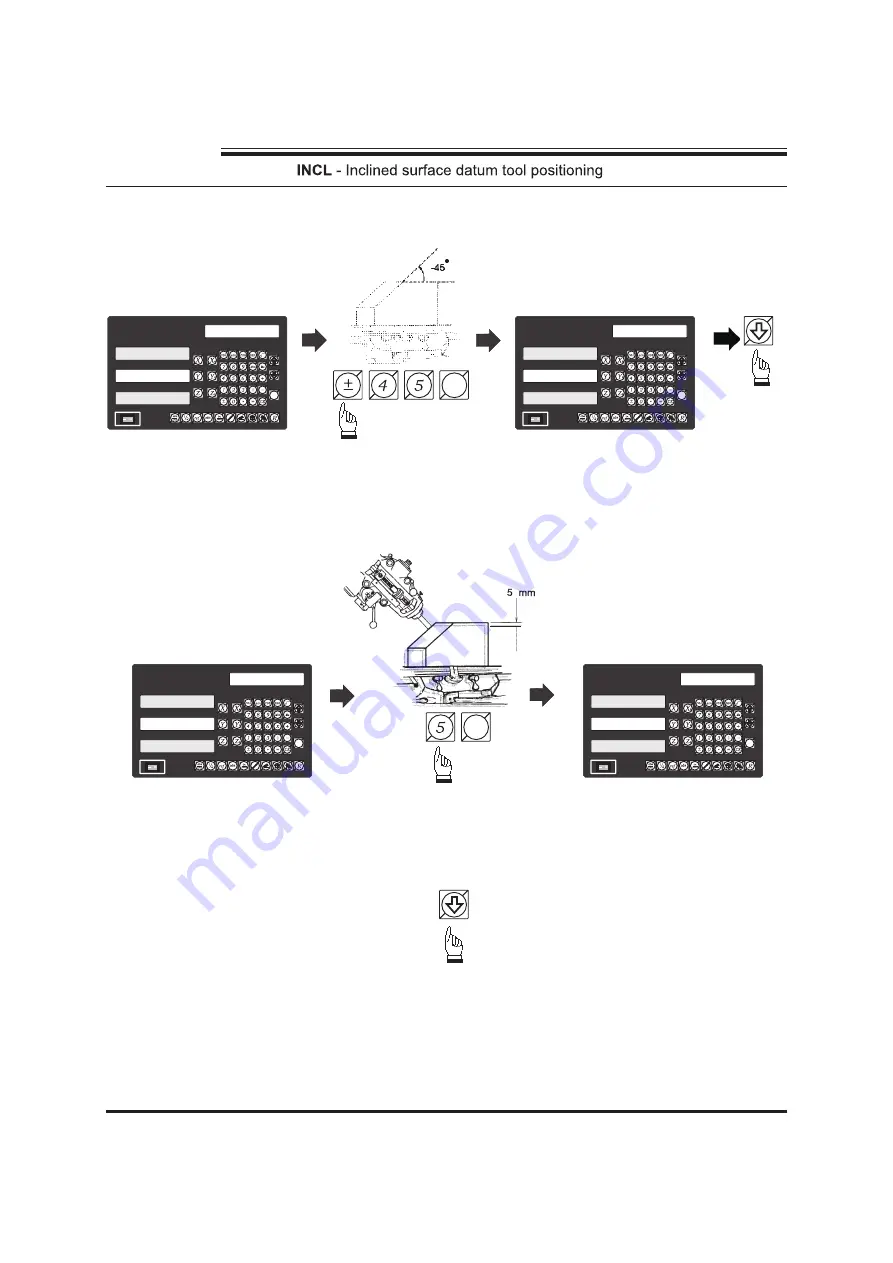
All  INCL machining parameters               to enter into INCL datuming mode
already entered  into RD-11M

step 3 :

Z increment per step machining (

)

Z STEP

step 2 :

enter inclined angle (

)

INCL ANG

next step

R

esson

Technologies

On

Off

RD-11M

R

esson

Technologies

ent

R

I

O

-45.000

INCL ANG

On

Off

RD-11M

R

esson

Technologies

ent

R

I

O

INCL ANG

0.000

On

Off

RD-11M

R

esson

Technologies

ent

R

I

O

Z STEP

5.000

On

Off

RD-11M

R

esson

Technologies

ent

R

I

O

Z STEP

0.000

ent

ent

Summary of Contents for RD-11M

Page 1: ...ople that Always Committed to Quality Technology Innovation Technologies Resson Technologies Co Ltd On Off RD 11M Resson Technologies ent R I O Digital Readout System Operation Manual Multi function R...

Page 2: ...ductor can render the equipment potentially dangerous Any intentional break is not permissible Please install the Linear Encoder finish after that switch on the Digital Readout Unit If switches on Dig...

Page 3: ...m 198 6feet min Quantizing error 1 count Power source AC 0V 0V 50 60Hz 20VA 10 23 Temperature fange Service 0 40 Storage 20 70 Linear Encoter Scales Electrical connector Inner shield N C N C N C N C I...

Page 4: ...t Basic Functions 1 REF datum memory 5 199 SubDatum Function 9 Built in Calculator 18 LHOLE Function 23 INCL Function 28 PCD Function 36 R Function 42 Simplified R Function 58 Shrinkage Calculation 75...

Page 5: ...1 Basic Functions Resson Technologies On Off RD 11M Resson Technologies ent R I O...

Page 6: ...mension Purpose 2 Resson Technologies On Off RD 11M Resson Technologies ent R I O On Off RD 11M Resson Technologies ent R I O 112 285 50 110 28 865 ABS 0 000 50 110 28 865 ABS On Off RD 11M Resson Tec...

Page 7: ...ero position in coordinate then switch to coordinate to continue machining ABS INC operations The operator is then free to zero the axes or preset any dimensions into any axis in coordinate for relati...

Page 8: ...Step 3 Then half the display coordinate using centre find function as per follows Now the X Axis zero point 0 000 is located at the X centre of the work piece 4 Resson Technologies On Off RD 11M Resso...

Page 9: ...5 Resson Technologies...

Page 10: ...s memory Then in case of the power failure or the RD 11M being switched off we can recover the work piece datum zero position by presetting the display zero position as the stored distance from the p...

Page 11: ...itches on the RD 11M step 3 move the machine reader head across the length of the transducer until digits display in RD 11M start to count step 1 To enter the ref function select the find mark FIND RE...

Page 12: ...ero position needed to be recovered move the machine across the length of the transducer select the RECALL 0 recall work zero Resson Technologies enter into function ref RECALL 0 recall work zero FIND...

Page 13: ...9 Resson Technologies...

Page 14: ...coordinates so all positions will move together ABS SDM when the zero position changes ABS 2 All relative distance data to can be entered directly into memory using the SdM ABS RD 11M keypad No need...

Page 15: ...1 Set up the work piece datum in co ordinate move the machine to the required subdatum position then zero ABS display co ordinate SdM Step 1 Set up the work piece datum in co ordinate ABS Switch to A...

Page 16: ...dm 2 set up already switch to sdm 2 coordinate display switch back to coordinate ABS display switch to sdm 1 coordinate display Set this point to ZERO sdm 1 set up already Resson Technologies On Off R...

Page 17: ...play switch back to coordinate ABS display switch to ABS coordinate display Operator can or to directly switch to the required subdatum coordinate sdm RD 11M s XY displays are referenced to the zero A...

Page 18: ...e zero sdm 2 switch to next up coordinate display sdm switch to next up coordinate display sdm switch to previous down coordinate display sdm Resson Technologies On Off RD 11M Resson Technologies ent...

Page 19: ...the subdatum point 1 sdm 1 When you enter the sdm co ordinate into the RD 11M the co ordinates displayed will indicate a negative sign This is correct because your tool is now located at zero positio...

Page 20: ...sdm Step 5 Set up the subdatum point 4 sdm 4 Key in the coordinate sdm 4 Switch to sdm 4 coordinate display Key in the coordinate sdm 3 Switch to sdm 3 coordinate display Resson Technologies SdM 4 On...

Page 21: ...e zero sdm 2 switch to next up coordinate display sdm switch to next up coordinate display sdm switch to previous down coordinate display sdm Resson Technologies On Off RD 11M Resson Technologies ent...

Page 22: ...18 Resson Technologies On Off RD 11M Resson Technologies ent R I O...

Page 23: ...ck to axis display 0 000 leaving the tool positioned at the calculated coordinate The built in calculator offers the following advantages 1 Operations are the same as commerically availiable calculato...

Page 24: ...11M is put in calculator mode the operation of RD 11M actually divided into two parts as follows normal X Y Z DRO display Normal calculator Resson Technologies On Off RD 11M Resson Technologies ent R...

Page 25: ...R I O 0 30 transfer the calculated result 108 675 onto the X axis for tool positioning to transfer calculated result to X axis X axis zero position is now preset at X 108 675 temporarily On Off RD 11...

Page 26: ...alculator mode you can to exit the calculator mode to return to normal coordinate display to continue the machining Resson Technologies On Off RD 11M Resson Technologies ent R I O X 108 675 0 000 45 6...

Page 27: ...23 Resson Technologies...

Page 28: ...Clockwise Y X After the above machining parameters are entered into RD 11M it presets all the Line Hole positions to 0 000 Operator can press or to select the Line Hole and then move the machine to d...

Page 29: ...Holes NO HOLE enter No of Holes NO HOLE No of Holes NO HOLE 4 Resson Technologies ent ent ent On Off RD 11M Resson Technologies ent R I O LIN ANG 30 000 On Off RD 11M Resson Technologies ent R I O LIN...

Page 30: ...Z display The operation is as follows presently in cycle LHOLE temporarily to normal swap XYZ coordinate display temporarily return to XYZ coordinate display Next Line Hole move the machine to display...

Page 31: ...ction cycle follow the procedure below presently in function cycle LHOLE return back to normal XYZ coordinate display Resson Technologies On Off RD 11M Resson Technologies ent R I O On Off RD 11M Ress...

Page 32: ...28 Resson Technologies...

Page 33: ...or rotary table to machine the inclined working surface easily However when the to work piece is too big be installed onto the incline table or the the only accuracy requirement is high solution is t...

Page 34: ...20 degree Install the work piece onto an rotary table at approxiately 20 degree step 1 select XY plane as the work plane INCL XY Approx 20 enter into function INCL select work plane XZ plane XY plane...

Page 35: ...ining parameters to enter into INCL datuming mode already entered into RD 11M zero the RD 11M since in INCL mode the Y display is set according to X tan ANG therefore zeroing the X axis also clear the...

Page 36: ...ntinue the incline angle alignment INCL presently in the temporarily XYZ coordinate display presently in cycle INCL Resson Technologies On Off RD 11M Resson Technologies ent R I O 78 560 5 000 23 450...

Page 37: ...e Negative Anti clockwise Inclines the mill head by 45 degree step 1 select XZ plane as the work plane INCL XZ 33 enter into function INCL select work plane XZ plane XY plane YZ plane select plane XZ...

Page 38: ...y entered into RD 11M step 3 Z increment per step machining Z STEP step 2 enter inclined angle INCL ANG next step Resson Technologies On Off RD 11M Resson Technologies ent R I O 45 000 INCL ANG On Off...

Page 39: ...up As a 2 Axis does not have Z Axis RD 11M the uses the RD 11M and to simiulate the Z axis movement simulate Z axis move down one step simulate Z axis move one step up move the axis of to X RD 11M di...

Page 40: ...36 Resson Technologies...

Page 41: ...tch hole position is reached After the above machining parameters are entered into RD 11M it presets all the pitch hole positions to 0 000 Operator can press or to select the pitch hole and then move...

Page 42: ...ep enter Centre Coordinate CENTRE enter Diameter DIA next step Resson Technologies ent ent ent ent On Off RD 11M Resson Technologies ent R I O 5 NO HOLE On Off RD 11M Resson Technologies ent R I O 80...

Page 43: ...into PCD drilling mode are already entered into RD 11M Operator can or to select the pitch hole then move the machine to display 0 000 to reach the pitch hole position Resson Technologies ent ent On...

Page 44: ...he hole drilling PCD presently in the temporarily XYZ coordinate display swap back to function cycle PCD return to function cycle PCD Last Pitch hole HOLE 1 picth hole no 1 move the machine to display...

Page 45: ...completed follow the under mentioned procedure presently in function cycle PCD returns to normal XYZ coordinate display Resson Technologies On Off RD 11M Resson Technologies ent R I O 0 000 0 000 HOL...

Page 46: ...R R R 42 Resson Technologies...

Page 47: ...ve your work piece to be machined in a CNC machine please bear in mind that ARC function is only cost effective and time saving under following conditions 1 One off job 2 Only simple ARC surface or ro...

Page 48: ...let RD 11M know the geometry of the ARC to be machined During installation the engineer will set the display direction same the the dial of the machine For a Taiwanese made knee type machine because o...

Page 49: ...Centre 0 0 20 R Example 4 Example 3 The R function of RD 11M allows the operator to machine R in XY XZ YZ plane as the illustration shows Even for 2 axis DRO RD 11M can calculate all the ARC machinin...

Page 50: ...mooth R option selected RD 11M will calculate the Z step increment so that the Max distance between each machining point is approximately the same R TOOL R TOOL XY plane R XZ YZ plane R MAX CUT max di...

Page 51: ...ollowing machining parameters have to be entered into the RD 11M 20 20 Centre 20 20 Datum 0 0 R End point 40 20 Start point 20 0 Z step 0 3 mm Tool Diameter 6mm Y positive direction Z positive directi...

Page 52: ...us R next step next step step 4 enter the Start point co ordinate XZ ST PT since two axis do not have axis RD 11M Z use axis to enter coordinate Y Z Resson Technologies On Off RD 11M Resson Technologi...

Page 53: ...ate Y Z step 6 enter the Tool diameter TOOL DIA step 7 select tool compensation direction next step next step R TOOL select R TOOL R TOOL next step Resson Technologies On Off RD 11M Resson Technologie...

Page 54: ...ible Z increment per step machining according to the curvature of ARC to make the interpolated point approximately equal to the MAX CUT entered RD 11M will calculate the best Z step increment so that...

Page 55: ...ning RD 11M uses the unused axis display to show the and Z dial turn number Z dial reading At the begining of the ARC machining the RD 11M will assume the Z axis dial is at zero position with the tool...

Page 56: ...3 Change increment to Z STEP 0 5 mm change the Z STEP now the increment Z STEP 0 5 mm currently increment Z STEP 0 3 mm If fixed option choosed the increment can be change anytime during the ARC mach...

Page 57: ...MAX CUT 0 3 mm Tool diameter 6mm End point 40 20 Centre 20 20 Datum 0 0 R Start point 20 0 20 20 To machine an plane using a 2 Axis XY R RD 11M Following machining parameters have to be entered into t...

Page 58: ...point coordinates ST PT step 4 enter the start point coordinates ST PT Resson Technologies On Off RD 11M Resson Technologies ent R I O R 20 000 On Off RD 11M Resson Technologies ent R I O 20 000 20 00...

Page 59: ...step next step next step enter the End point coordinates ENd PT step 5 enter End point s coordinate ENd PT Resson Technologies R TOOL R TOOL R TOOL ent On Off RD 11M Resson Technologies ent R I O 40...

Page 60: ...or to select the interpolated points along the ARC curvature then move the machine to display 0 000 to arrive at the ARC curvature position next point R last point R move the machine to display 0 000...

Page 61: ...YZ coordinate display swap back to R cycle to continue the machining mode R presently in the temporarily XYZ coordinate display swap back to function cycle R return to function cycle R Resson Technolo...

Page 62: ...R R R 58 Resson Technologies...

Page 63: ...t types of ARC are used for machining The RD 11M has therefore incorporated those 8 type of R and the operator must just select the type of R they need to machine their part and input the Radius tool...

Page 64: ...specified as the machining step increment For XZ YZ plane R under normal condition the Z step increment is fixed and to be specified as the machining step increment MAX CUT max distance between inter...

Page 65: ...n arc which is less than 90 degrees it is necessary to divide this arc machining into two parts Use preset type R 2 position the tool at the ARC starting point surface of the work piece centre in this...

Page 66: ...type R TYPE 1 8 step 2 enter Tool diameter TOOL DIA step 4 next step next step next step Resson Technologies On Off RD 11M Resson Technologies ent R I O TYPE 1 8 2 On Off RD 11M Resson Technologies en...

Page 67: ...according to the curvature of ARC to make the interpolated point approximately equal to the MAX CUT entered RD 11M will calculate the best Z step increment so that the Max distance between each machin...

Page 68: ...chining the RD 11M uses the unused axis display to display the Z dial turn number Z dial reading and At the beginning of the ARC machining the RD 11M will assume the Z axis dial at zero position with...

Page 69: ...ily XYZ coordinate display swap back to function cycle R return to function cycle R Change increment to Z STEP 0 5 mm change the Z STEP now the increment Z STEP 0 5 mm currently increment Z STEP 0 3 m...

Page 70: ...itive direction Example To machine an plane using 2 Axis XY R RD 11M R 80 mm Start point position the tool at the start point of the ARC select work plane plane XY R R XY step 1 enter into Simpflified...

Page 71: ...e R TYPE 1 8 next step enter Radius R next step enter Tool diameter TOOL DIA next step Resson Technologies On Off RD 11M Resson Technologies ent R I O TYPE 1 8 3 On Off RD 11M Resson Technologies ent...

Page 72: ...RD 11M R TOOL select R TOOL R TOOL next step enter Max Cut MAX CUT MAX CUT 0 3 mm R R R R Operator can or to select the interpolated points along the ARC curvature then move the machine to display 0 0...

Page 73: ...return to XYZ coordinate display swap back to R cycle to continue the machining mode R presently in the temporarily XYZ coordinate display swap back to function cycle R return to function cycle R Res...

Page 74: ...n only machine an arc which is less than 90 degrees it is necessary to divide this arc machining into two parts posit the tool at the ARC starting point First Part Second Part Use preset type R 7 Use...

Page 75: ...E 1 8 0 TYPE 1 8 next step enter Radius R next step enter Tool diameter TOOL DIA next step Resson Technologies On Off RD 11M Resson Technologies ent R I O TYPE 1 8 6 On Off RD 11M Resson Technologies...

Page 76: ...int approximately equal to the MAX CUT entered RD 11M will calculate the best Z step increment so that the Max distance between each machining point approximately the same All simplified R funtion to...

Page 77: ...or YZ plane R machining it is necessary to carefully position the Z axis to obtain a precise Z position As there is no Z axis in the two axis RD 11M and in order that the operator can easily guide an...

Page 78: ...mporarily return to XYZ coordinate display swap back to R cycle to continue the machining mode R presently in the temporarily XYZ coordinate display swap back to function cycle R return to function cy...

Page 79: ...75 Resson Technologies...

Page 80: ...mistake occurs There is also no easy method of verifying the calculated dimensions and it is too easy to make mistakes subjecting the operator to heavy psychological pressure 3 Mould work has to be co...

Page 81: ...ension of 27mm The current position of X axis is 123 45 therefore 123 45 mm expands 123 45 x 1 005 124 067 Calculation result will display in the message window 27mm expand 27 x 1 005 27 135 Calculati...

Page 82: ...rator s calculated dimensions marked on the drawing by using the Expand and Shrink toggle function to switch between real dimension display and shrinkage compensated dimension display Because the disp...

Page 83: ...real dimension display return to normal display Resson Technologies On Off RD 11M Resson Technologies ent R I O SHRINK 105 000 105 000 105 000 On Off RD 11M Resson Technologies ent R I O ABS 100 000 1...

Page 84: ...o calculate the reduced dimensions one by one 2 Set the RD 11M to Expand Compensation i e For plastic material ABS it s shrink factor is 1 005 1 Entering the SHRINK FACTOR The actual dimension are now...

Page 85: ...ensions When the RD 11M is in shrink compensation mode if the operator wants to return to normal real dimension display press or Currently in shrink compensation mode normal real dimension display ret...

Page 86: ...E QUIT forms part of the dial parameters for a milling machine and specifies one turn of Z dial travel specifies the direction of count for each axis permits linear error compensation to be input ente...

Page 87: ...please press 8 key then DRO enters into the RESET function power on the DRO then DRO starts the self test function when VER 9MA appears in display window please press key when some messages are displa...

Page 88: ...mpleted then start to enter into the test procedure of display light Turn off the DRO after complete the reset then power on the DRO once again 84 Resson Technologies Digital Readout Setup Function On...

Page 89: ...ediately then the DRO starts entering into the SETUP function The SETUP procedure is written in a menu mode which enables you to scroll through the top level options and enter configure and exit the s...

Page 90: ...nto the direction setting function the 0 represents a positive 1 represents a negative 3 Press key to select the DIRECTN counting direction function Press key to return to the last function Press or k...

Page 91: ...Axis 5 Press key to make you setting then press key to select the RAD DIA function Press key into the RAD DIA function 87 Resson Technologies Digital Readout Setup Function ent On Off RD 11M Resson Te...

Page 92: ...to the setting function i e your setting value is 2 500mm For a Taiwanese type milling machine the travel is 2 5mm usually Press key to set up X Y or Z Axis to RAD DIA then press key to make your sett...

Page 93: ...e UP DOWN keys to move to the next menu item For a Taiwanese knee type milling machine the minimum increment is 0 02mm 8 Press key to select the R MODE function Press key to make your setting then pre...

Page 94: ...dy for machining operations If use the error compensation function you must turn off the DRO then power on the DRO again otherwise your compensated value will invalid 90 Resson Technologies Digital Re...

Reviews: