background image

PROCEDURE 6—FILTER ARRANGEMENT

WARNING: Never operate unit without a filter or with filter access door removed. Failure to follow this warning could

result in fire, personal injury, or death.

The 2 factory-supplied filters are shipped in the blower compartment. After the return-air duct has been connected to the furnace, install the filters
in a V-formation inside the return-air plenum. See Fig. 8 and Table 4 for horizontal applications. Horizontal filter retainers must be field supplied.
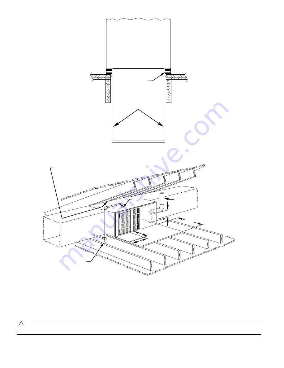
See Fig. 9 for downflow applications.

Fig. 6—Furnace, Plenum, and Subbase Installed on a Combustible Floor

A78651

DOWNFLOW

SUBBASE

SHEET METAL

PLENUM

FURNACE

(OR COIL CASING

WHEN USED)

Fig. 7—Typical Attic Installation

A82178

30-IN. MIN
WORK AREA

6

″ 

MIN

FLUE VENT

GAS
ENTRY

24

24

SHEET
METAL

SEDIMENT TRAP

LINE CONTACT ONLY PERMISSIBLE BETWEEN
LINES FORMED BY INTERSECTIONS OF
THE TOP AND TWO SIDES OF THE FURNACE
JACKET AND BUILDING JOISTS,
STUDS, OR FRAMING.

—8—

Summary of Contents for GB3AAV

Page 1: ...a Working Platform 7 Install Furnace 7 HORIZONTAL CRAWLSPACE INSTALLATION 7 8 FILTER ARRANGEMENT 8 9 GAS PIPING 9 10 ELECTRICAL CONNECTIONS 11 12 115 v Wiring 11 24 v Wiring 11 Accessories 11 12 VENTI...

Page 2: ...aces are available in sizes 50 000 through 135 000 Btuh input capacities The design of the downflow horizontal gas fired furnace is A G A C G A certified for natural and propane gas and for installati...

Page 3: ...monoxide poisoning explosion fire electrical shock or other conditions which may cause personal injury loss of life or property damage Consult a qualified installer service agency local gas supplier o...

Page 4: ...nds which include fluoride chloride bromide and iodide These elements are found in aerosol sprays detergents bleaches cleaning solvents salts air fresheners and other household products CAUTION The op...

Page 5: ...m outdoors See Fig 3 2 All air from outside the structure a If combustion air is taken from outdoors through vertical ducts the openings and ducts MUST have at least 1 sq in of free area per 4000 Btuh...

Page 6: ...8 19 7 16 21 19 7 8 19 5 8 19 7 16 24 1 2 23 7 16 19 5 8 19 7 16 These dimensions apply when a model CB or CD Evaporator Coil casing is to be installed B Installation On a Combustible Floor 1 Cut and...

Page 7: ...shield on platform in front of louvered control panel as shown in Fig 7 PROCEDURE 5 HORIZONTAL CRAWLSPACE INSTALLATION The furnace can be installed horizontally with either the LH or RH side up In a c...

Page 8: ...turn air plenum See Fig 8 and Table 4 for horizontal applications Horizontal filter retainers must be field supplied See Fig 9 for downflow applications Fig 6 Furnace Plenum and Subbase Installed on a...

Page 9: ...anadian installations must be installed in accordance with NSCNGPIC and all authorities having jurisdiction The gas supply line should be a separate line directly from the meter to the furnace if poss...

Page 10: ...d only to the male threads of the joints This pipe dope must be resistant to the action of propane gas Install an accessible manual shut off valve upstream of the furnace gas controls and within 72 in...

Page 11: ...n electrical shock fire or death B 24 v Wiring Make field 24 v connections at the 24 v terminal strip See Fig 11 Connect terminal Y as shown in Fig 13 for proper operation in cooling mode Use AWG No 1...

Page 12: ...08 230 VOLT SINGLE PHASE WHT BLK WHT BLK If any of the original wire as supplied must be replaced use same type or equivalent wire NOTE Connect Y terminal as shown for proper operation W Y GND THERMOS...

Page 13: ...Ignitor warm up At the end of the prepurge period the ignitor is energized for a 17 sec ignitor warm up period c Ignition sequence When the ignitor warm up period is completed the gas valve opens per...

Page 14: ...DISCONNECT SWITCH AND THE FURNACE JUNCTION BOX JB 5 THIS WIRE MUST BE CONNECTED TO FURNACE SHEETMETAL FOR CONTROL TO DETECT FLAME 6 FACTORY CONNECTED WHEN LGPS NOT USED 7 REPLACE ONLY WITH A 3 AMP FUS...

Page 15: ...e to follow this warning could result in fire explosion personal injury or death 2 Component test The furnace control allows all components except gas valve to be run for a short period of time This f...

Page 16: ...40 38 39 3 7 3 2 3 5 40 38 39 3 8 3 3 3 6 905 42 3 5 41 42 3 2 3 6 41 42 3 4 3 7 40 41 3 2 3 5 40 41 3 3 3 6 40 41 39 3 4 3 7 3 2 40 41 39 3 5 3 8 3 3 40 39 3 6 3 4 40 38 39 3 7 3 2 3 5 920 42 3 4 42...

Page 17: ...In the United States gas input on unit rating plate is for altitudes up to 2000 ft Ratings for altitudes over 2000 ft must be 4 percent less for each 1000 ft above sea level To obtain the adjusted al...

Page 18: ...0 60 62 64 66 68 60 58 56 54 53 120 116 112 109 106 300 290 281 273 265 25 26 27 28 29 144 138 133 129 124 288 277 267 257 248 720 692 667 643 621 70 72 74 76 78 51 50 48 47 46 103 100 97 95 92 257 25...

Page 19: ...g the heating cycle length NOTE When using an electronic thermostat set cycle rate for 3 cycles per hr E Check Safety Controls The flame sensor gas valve and pressure switch were all checked in the St...

Page 20: ...did not function properly and correct condition e Turn off 115 v power to furnace f Reconnect inducer motor wires replace control door and turn on 115 v power to furnace 4 Check auxiliary limits when...

Reviews: