(m) If it is necessary to connect the inductance load such as a
monitor or a laser printer to the UPS, the start-up power should
be used for calculating the capacity of the UPS, as its start-up
power consumption is too big when it is started.
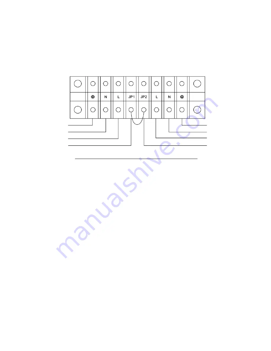
Input and output Terminal Block wiring diagram
Important notes: If the UPS is used in single mode, JPI
and JP2 must be connected by 10AWG(6mm2). If the
UPS is used in parallel mode, the Jumper between
JP1 and JP2 must be removed.
4.3 Procedure for connecting the long backup time UPS with the
external battery
1. The nominal DC voltage of external battery pack is 240VDC. Each
battery pack consists of 20 pieces of 12V maintenance free batteries
in series. To achieve longer backup time, it is possible to connect
multi-battery packs, but the principle of “same voltage, same type”
should be strictly followed.
Input Ground
Input Neutral
Input Line
JP1
Output Ground
Output Neutral
Output Line
JP2
12
Summary of Contents for RP-UPH104T
Page 1: ...USER S MANUAL On Line 6K 10KVA Uninterruptible Power Supply...
Page 19: ...Battery Status Output Power Temperature History Record 18...
Page 36: ...DB 9 Interface of AS400 communication protocol 35...
Page 39: ...Appendix 1 Outline Description and Back Panel Back view of 6K Back view of 6KL 38...
Page 40: ...Back view of 10K Back view of 10KL 39...
Page 41: ...40...


