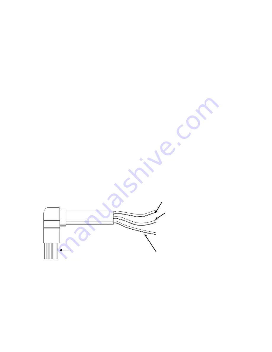
2. The connector of the external battery cable is used to plug into the
external battery socket of the UPS. The other end of the external
battery cable is made of three open wires with ring terminals to
connect with the external battery pack(s). The procedure of installing
battery bank should be complied with strictly.
(a) A DC breaker must be connected between the battery pack and
the UPS. The capacity of breaker must be not less than the
data specified in the general specification.
(b) Set the battery pack breaker in “OFF” position and connect the
20 pieces of batteries in series.
(c) Must connect the external battery cable to the battery first. The
positive pole of the battery is connected to the UPS in parallel
with blue and brown wires; the negative pole of the battery is
connected to the UPS in parallel with black and white wires; the
green and yellow ribbon wire is connected to the ground of the
battery cabinet.
The blue & brown wires for connection to the
positive terminal of the battery pack output.
The black & white wires
for connection to the
Negative terminal of the
battery pack output.
The green and yellow ribbon
wires are for connection to the
Ground of the battery cabinet.
The receptacle
for connecting
the UPS.
13
Summary of Contents for RP-UPH104T
Page 1: ...USER S MANUAL On Line 6K 10KVA Uninterruptible Power Supply...
Page 19: ...Battery Status Output Power Temperature History Record 18...
Page 36: ...DB 9 Interface of AS400 communication protocol 35...
Page 39: ...Appendix 1 Outline Description and Back Panel Back view of 6K Back view of 6KL 38...
Page 40: ...Back view of 10K Back view of 10KL 39...
Page 41: ...40...


