background image

Electrical drawings MVV 2000 DC

L3 

L2 

L1 

CN204 

CN205 

CN206 

L1 

CN200 

CN201 

CN202 

L2 

L3 

CN203 

FILTER-8R0.D.1.1-1 

202302141048 

(1.5) 2012-10-10 

CN214 

CN213 

CN209  CN210 

CN212 

CN211 

CN150 

RY1 

FUSE1 / T250V/8A 

CN208 

CN207 


4


1

2

3

9

10

11

5

6

7

8

12

13

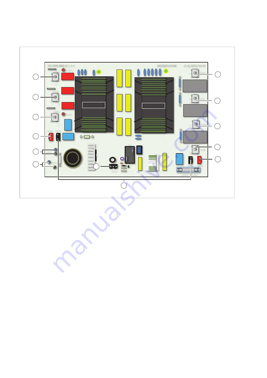
Fig. 36: Electrical drawings MVV 2000 DC power pcb

1:

Connection with the three-phase inverter

(contact: 1)

2:

Connection with the three-phase inverter

(contact: 2)

3:

Connection with the three-phase inverter

(contact: 3)

4:

Connection to the control board (contact: CN 41)

5:

Connection to the IPM board (contact: CN 2)

6:

Connection to the distribution board

(contact: CN 101)

7:

Connection to the control board

(contact: CN 150)

8:

Connected with each other

9:

Connection with the terminal block, power

supply (contact: L3)

10: Connection with the terminal block, power

supply (contact: L2)

11: Connection with the terminal block, power

supply (contact: L1)

12: Connection with the terminal block, power

supply (contact: N)

13: Connection to the control board

(contact: CN 250)


REMKO MVV...DC


40

Summary of Contents for MVV 1200 Dc

Page 1: ...Assembly and operating instructions Read the instructions prior to performing any task REMKO MVV DC MVV 1200 DC MVV 1600 DC MVV 2000 DC Inverter outdoor units 0030 2015 04 Edition 6 en_GB...

Page 2: ...g inal Read these operating instructions carefully before commis sioning using this device These instructions are an integral part of the system and must always be kept near or on the device Subject t...

Page 3: ...2 Combinations 19 4 Operation 21 5 Installation instructions for qualified personnel 21 5 1 Important notes prior to installation 21 5 2 Wall openings 22 5 3 Installation materials 22 5 4 Selection of...

Page 4: ...13 Shutdown 62 14 Exploded view of the unit and spare parts list 63 14 1 Exploded view of the unit 63 14 2 Spare parts list 64 15 Index 66 REMKO MVV DC 4...

Page 5: ...ded may be fatal or cause serious injury WARNING This combination of symbol and signal word warns of a potentially hazardous situation which if not avoided may be fatal or cause serious injury CAUTION...

Page 6: ...walls or floors n Mobile units must be set up securely on suit able surfaces and in an upright position Sta tionary units must be permanently installed for operation n The units and components should...

Page 7: ...otection and recycling Disposal of packaging All products are packed for transport in environ mentally friendly materials Make a valuable contri bution to reducing waste and sustaining raw mate rials...

Page 8: ...2480 3295 3090 Operating pressure max kPa 4200 Air flow rate max m h 6000 10800 Sound power level 3 dB A 66 63 65 62 70 67 Sound pressure level max 3 dB A 58 55 57 52 59 56 Power supply V Hz 400V 3 N...

Page 9: ...Serial number 1226C8001 1227C8001 1239C8001 EDP no 1623600 1623605 1623610 1 Outside temperature TK 35 C FK 24 C max air flow volume 5m pipe length 2 Outside temperature TK 7 C FK 6 C max air flow vo...

Page 10: ...10 8 kW 1 54 kW 12 9 kW 1 89 kW 20 C 8 7 kW 1 33 kW 10 8 kW 1 69 kW 12 9 kW 2 19 kW 25 C 8 7 kW 1 49 kW 10 8 kW 2 01 kW 12 9 kW 2 61 kW 35 C 8 7 kW 2 04 kW 10 8 kW 2 78 kW 12 17 kW 3 27 kW 44 C 8 7 k...

Page 11: ...3 87 kW 10 C 10 04 kW 3 77 kW 10 kW 3 97 kW 9 96 kW 4 17 kW 0 C 13 01 kW 4 2 kW 11 88 kW 3 79 kW 10 33 kW 3 21 kW 7 C 13 39 kW 3 53 kW 11 88 kW 3 06 kW 10 33 kW 2 62 kW 15 C 13 39 kW 2 79 kW 11 88 kW...

Page 12: ...kW 20 C 11 24 kW 1 85 kW 13 95 kW 2 36 kW 16 66 kW 3 05 kW 25 C 11 24 kW 2 07 kW 13 95 kW 2 8 kW 16 66 kW 3 63 kW 35 C 11 24 kW 2 83 kW 13 95 kW 3 86 kW 15 72 kW 4 54 kW 44 C 11 24 kW 3 59 kW 13 95 kW...

Page 13: ...W 10 C 12 93 kW 5 18 kW 12 87 kW 5 45 kW 12 82 kW 5 73 kW 0 C 16 76 kW 5 77 kW 15 3 kW 5 21 kW 13 31 kW 4 42 kW 7 C 17 24 kW 4 86 kW 15 3 kW 4 21 kW 13 31 kW 3 6 kW 15 C 17 24 kW 3 83 kW 15 3 kW 3 35...

Page 14: ...3 86 kW 20 C 14 5 kW 2 71 kW 18 kW 3 46 kW 21 5 kW 4 48 kW 25 C 14 5 kW 3 04 kW 18 kW 4 1 kW 21 5 kW 5 33 kW 35 C 14 5 kW 4 15 kW 18 kW 5 66 kW 20 29 kW 6 67 kW 44 C 14 5 kW 5 27 kW 18 kW 6 88 kW 19 3...

Page 15: ...C 16 73 kW 6 46 kW 16 66 kW 6 8 kW 16 59 kW 7 15 kW 0 C 21 68 kW 7 19 kW 19 8 kW 6 5 kW 17 22 kW 5 51 kW 7 C 22 31 kW 6 06 kW 19 8 kW 5 25 kW 17 22 kW 4 49 kW 15 C 22 31 kW 4 78 kW 19 8 kW 4 18 kW 17...

Page 16: ...t output may be installed Operation takes place as standard via an infra red remote control The outdoor unit consists of a cycle with a compressor fin condenser electronic expansion valve and a conden...

Page 17: ...20 21 22 23 25 26 29 27 28 30 Fig 8 Cooling cycle schematic MVV 1200 DC see next page for legend 18 PSH EC EC PSL EC M 1b 2 4 5 6 7 8 9 3 19 15 16 17 13 12 11 10 14 24 20 21 22 23 25 26 29 27 28 30 Fi...

Page 18: ...t off valve FL 16 Shut off valve SL 17 Re injection valve SV6 SV2 heating mode ta 3 C and f 52Hz 18 Heat gas bypass valve SV5 SV4 t5 105 C 19 ND collector 20 Liquid separator 21 Crankcase heating 22 P...

Page 19: ...take place with consideration to the local conditions Outdoor unit Type Power Power factor Maximum refrigerating capacity of the indoor units to be connected MVV 1200 DC 12 0 kW 130 15 6 kW MVV 1600 D...

Page 20: ...5 5 5 6 5 6 6 Fig 12 Connection possibilities on multiple levels A Outdoor area B Indoor area 1 Outdoor unit 2 Indoor units of the series MVD or MVW 3 Distributor 4 Y distributor 5 Main line 6 Ancilla...

Page 21: ...ssary also insulate the condensate drainage line n Select an installation location which allows air to freely flow through the air inlet and outlet see Chapter 5 5 Minimum clearances on page 24 n Do n...

Page 22: ...Euroraster dimensions How ever they can also be installed in suspended ceilings with different dimensions Take into account the installation height of the equipment Outdoor unit The outdoor unit is de...

Page 23: ...tdoor unit An optional wall bracket is available as an accessory 20 cm 1 Fig 15 Minimum clearance to snow 1 Snow Installation inside buildings n Ensure that heat can dissipate adequately when placing...

Page 24: ...ution E C B A D 1 2 200 120 1500 120 120 1000 1000 1000 500 1000 1 2 A B C Fig 17 Minimum clearances outdoor units and indoor units all measurements in mm A Outdoor unit MVV B Indoor unit MVW C Indoor...

Page 25: ...upport the static load refer to the installa tion instructions for the brackets 4 Ensure that structure borne sound is not transferred to parts of the building Use vibra tion dampers to reduce the eff...

Page 26: ...frigerant piping 1 Flanging tool Fig 20 Correct flange shape 2 1 Fig 21 Tightening the fitting 1 Tighten with the first open ended spanner 2 Counter with the second open ended spanner Pipe dimension i...

Page 27: ...refrigerant piping When combining the outdoor unit with the different indoor units the refrigerant piping connection may differ Install the corresponding expansion fittings sleeves on the distributors...

Page 28: ...9m 1 4 6m 1 4 7m 3 8 8m1 4 8m 3 8 2m 3 8 27m 3 8 1 4 Fig 22 Example combination for calculating the supplementary refrigerant to be added A Outdoor area B Indoor area 1 Outdoor unit 2 Indoor units of...

Page 29: ...ler Fig 23 Sketch for determining the refrigerant quantity to be added Component Number Fill factor Additional fill quantity Length of the liquid pipe 1 4 m 0 023 kg m kg Length of the liquid pipe 3 8...

Page 30: ...g Practical limit value R410A 0 44 kg m3 8 01 kg 0 44 kg m3 18 20 m3 This equates to a min room size of the smallest air conditioned room of approx 2 7 x 2 7 x 2 5 m 7 Condensate drainage connection a...

Page 31: ...apour diffusion proof insulation n When operating the unit at outdoor tempera tures below 4 care must be taken that the condensate drainage line is anti freeze pro tected The lower part of the housing...

Page 32: ...he following instructions n Customers should install a terminal box in the vicinity of the outdoor unit We recommend using a main repair switch Figure 9 n The power supply to the indoor units takes pl...

Page 33: ...rminal block supply line B Terminal block communication 1 Power supply 2 Not connected 3 Control line 1 2 3 A B Fig 29 Electrical wiring of the lines to the outdoor unit MVV 2000 DC A Terminal block s...

Page 34: ...unit supply 3 x 1 5 mm2 Outdoor unit supply 5 x 2 5 mm2 Communication line 3 x 0 75 mm2 Shielded Central remote control 3 x 0 75 mm2 Shielded All figures are minimum cross sections The actual cross s...

Page 35: ...switch high pressure switch 3 Heat gas probe 4 Probe condenser register probe ambient air 5 Connection with the terminal block control line 6 Connection to the inverter board contact CN 5 7 Connectio...

Page 36: ...the control board contact CN 201 4 Connection to the C2 capacitor contact plus 5 Compressor 6 Connection to the C2 capacitor contact minus 7 Connection to the three phase inverter contact 1 8 Connect...

Page 37: ...e switch 3 Heat gas probe 4 Probe condenser register probe ambient air 5 Connection with the terminal block control line 6 Connection to the inverter board contact CN 5 7 Connection to the inverter bo...

Page 38: ...the control board contact CN 201 4 Connection to the C2 capacitor contact plus 5 Compressor 6 Connection to the C2 capacitor contact minus 7 Connection to the three phase inverter contact 1 8 Connect...

Page 39: ...probe 4 Connection with the communication terminal block contact CN 4 5 Low pressure switch high pressure switch 6 Connection to the IPM board contact CN 5 7 Connection to the CAP3 capacitor contact...

Page 40: ...ntact 2 3 Connection with the three phase inverter contact 3 4 Connection to the control board contact CN 41 5 Connection to the IPM board contact CN 2 6 Connection to the distribution board contact C...

Page 41: ...ressing ON 1 2 3 Reset addressing 9 Before commissioning After leak testing has been successfully com pleted connect the vacuum pump via the pressure gauge station to the valve connections on the out...

Page 42: ...ctive caps from the valves 2 Start the commissioning procedure after evacuating the pipe system by briefly opening the shut off valves on the outdoor unit until the pressure gauge indicates a pressure...

Page 43: ...Fig 37 Check key on the outdoor unit s board 1 Check key 2 Force Cool key The following parameters are shown in the display during operation Operating status Display Standby Number of indoor units Com...

Page 44: ...5 Temperature probe condenser register Current value 6 Temperature probe ambient air Current value 7 Temperature heat gas probe Current value 8 Surface temperature of the cooling fins Current value 9...

Page 45: ...r switching on is too short Does a restart occur after around 5 minutes Schedule longer wait times Operational temperature range too low exceeded Are the fans on the units still working Observe temper...

Page 46: ...essive temperature inverter module Heat build up in board space on page 51 P1 High pressure fault Connections faulty fan motor faulty register outdoor unit dirty high pressure switch faulty on page 52...

Page 47: ...it and outdoor unit E4 Probe T3 or T4 defective E5 Overload protection E6 Condenser fan fault E7 Heat gas pipe probe defective EA Non functional Eb 2x E6 within 10 minutes P0 Compressor excessive temp...

Page 48: ...re establish power supply start system YES Is the communication line correctly wired NO Correctly wire communication line YES Has shielded cable been used NO Use shielded cable YES Is a fixed resisto...

Page 49: ...control board NO Replace the control board YES Is the connection between the inverter board and power pcb CN12 established correctly NO Establish the connection correctly YES Is the voltage between P...

Page 50: ...ounted on the board NO Correctly mount the fan motor on the board YES Can the shaft of the fan motor be rotated easily NO Replace fan motor YES Is the output voltage of the board between the black and...

Page 51: ...the probe on the circuit board YES Is the probe visibly damaged YES Replace probe NO Are the probe resistance values OK See Chapter 11 3 Resistances of the temperature probes on page 59 NO Replace pr...

Page 52: ...is back inside the usable limits YES Is the plug of the pressure switch correctly mounted on the board NO Correctly mount the plug YES Is the refrigerant piping kinked YES Suction refrigerant back off...

Page 53: ...til the unit is back inside the usable limits YES Is the plug of the pressure switch correctly mounted on the board NO Correctly mount the plug YES Is the refrigerant piping kinked YES Suction refrige...

Page 54: ...ing NO See on page 50 YES Is the ambient temperature of the outdoor unit above the usable limit NO Switch off unit and wait until the unit is back inside the usable limits YES Is the refrigerant pipin...

Page 55: ...in the cooling cycle YES Fix leak top up refrigerant NO Is the probe T5 correctly mounted on the board NO Correctly mount the probe on the circuit board YES Is the probe visibly damaged YES Replace p...

Page 56: ...he probe resistance values OK See Chapter 11 3 Resistances of the temperature probes on page 59 NO Replace probe YES Is the heat exchanger of the outdoor unit heavily soiled YES Carefully clean the re...

Page 57: ...the motor windings of the compressor U V 0 5 5 0 Ohm V W 0 5 5 0 Ohm W U 0 5 5 0 Ohm NO Replace compressor YES Is the voltage between the capacitors of the compressor 540 600 Volt NO Replace defective...

Page 58: ...sure test and evacuate put back into operation NO Is too much refrigerant in the cooling cycle YES Suction off refrigerant and refill system NO Wait until the temperature at probe T2 is below 50 C and...

Page 59: ...88 37 5 87 6 25 50 38 5 63 7 24 19 39 5 40 8 22 57 40 5 18 9 21 81 41 4 96 10 20 72 42 4 76 11 19 69 43 4 57 Temp C Resistance Ohm Temp C Resistance Ohm 44 4 39 79 1 21 45 4 21 80 1 17 46 4 05 81 1 1...

Page 60: ...61 4 11 104 6 6 247 8 12 99 69 5 234 9 13 95 05 4 222 8 14 90 66 3 211 4 15 86 49 Temp C Resistance Ohm Temp C Resistance Ohm 16 82 54 51 18 96 17 78 79 52 18 26 18 75 24 53 17 58 19 71 86 54 16 94 20...

Page 61: ...ip ment is disconnected from the voltage supply and secured to prevent accidental switch on Care n Ensure the unit is protected against dirt mould and other deposits n Only clean the unit using a damp...

Page 62: ...ecirculation mode or in cooling mode at maximum temperature to extract any residual humidity from the unit 2 Shut down the system using the remote con trol 3 Switch off the electrical power supply to...

Page 63: ...1 Exploded view of the unit 1 2 11 6 5 7 4 10 16 3 3 6 8 9 12 13 14 15 17 18 19 21 20 22 Fig 39 Exploded view of the unit MVV 1200 2000 DC We reserve the right to modify the dimensions and design as...

Page 64: ...acitor 10 Shut off valve suction pipe 11 Shut off valve liquid pipe 12 Reversing valve 13 Inverter board 14 Capacitor compressor 15 Control board with display 16 Electronics module cpl 17 Electronic e...

Page 65: ...rature probe ambient air Temperature probe outlet condenser Temperature probe heat gas Solenoid valve SV2 SV4 SV7 Solenoid valve heat gas bypass SV5 Solenoid valve re injection SV6 Solenoid valve coil...

Page 66: ...ay 46 47 Malfunctions Checks 45 Possible causes 45 Remedial measures 45 Minimum clearances 24 O Ordering spare parts 64 65 P Propellant in accordance with Kyoto Protocol 9 R Resistances Temperature pr...

Page 67: ......

Page 68: ...t as advisers to our customers in air conditioning and heating technology SFlbCustomer Service Our equipment operates precisely and reliably However in the event of a fault REMKO customer service is q...

Reviews: