4.7
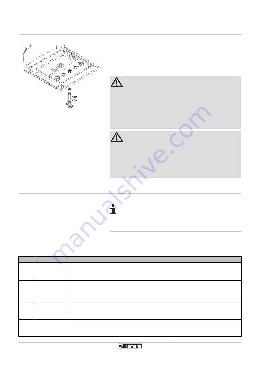
Gas connection
1. Remove the anti-dust plug located on the gas connection
GAS/
GAZ
under the boiler.
2. Connect the gas inlet pipe.
3. Mount a gas isolation valve on this pipe, directly under the boiler.
4. Connect the gas pipe to the gas shut off valve.
WARNING
4
Close the main gas valve before starting work on the
gas pipes.
4
Before mounting, check that the gas meter has
sufficient capacity. To do this, you should keep in
mind the consumption of all domestic appliances.
4
If the gas meter has too low a capacity, inform the
energy supply company.
CAUTION
4
Ensure that there is no dust in the gas pipe. Blow into
the pipe or shake it before mounting.
4
We recommend installing a gas filter on the gas pipe
to prevent clogging of the gas valve unit.
4
Connect the gas pipe in accordance with prevailing
standards and regulations.
4.8
Connections for the air and exhaust pipes
¼
The boiler is suitable for the following types of flue
gas connections. See chapter: "Certifications", page 7
4.8.1.
Classification
The table specifies this classification in detail according to
[
.
Type
Execution
Description
B23
B23P
(1)
Open
4
Without fire-stop approval.
4
Exhaust of combustion gases above the roof.
4
Air in the installation room.
B33
Open
4
Without fire-stop approval.
4
Common exhaust of combustion gases above the roof.
4
Common exhaust of combustion gases mixed in the air, air in the installation room (special
construction).
C13
Closed
4
Vent in the outside wall.
4
The opening for the air-supply inlet is located in the same pressure zone as the vent (For
example, a common passage through the outside wall).
(1) Including the pressure classification P1
(2) EN483: 0,5 mbar suction by pressure reduction
(3) An under pressure of 4 mbar is possible
(4) See table for minimum sizes of duct or sleeving
T001575-B
4. Installation
Calenta 25s - 28c - 35s - 40c
32
040412 - 7600585-01


