background image

CRANKCASE AND CRANKSHAFT

English – 43

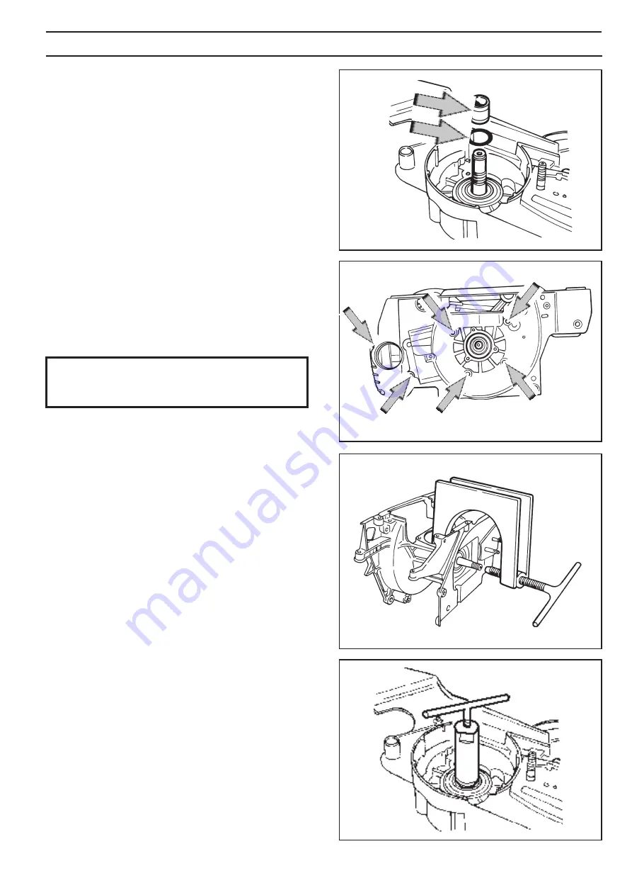
 Fig. 1

 Fig. 2

 Fig. 3

 Fig. 4

1.   Before the crankcase can be split, the following  


components must be removed:


A.  

Chain and guide bar.


B.  

Recoil starter.


C.  

Electrical system.


D.  

Centrifugal clutch.


E.  

Lubrication system.

 F. 

 Carburettor.

 G. 

 Silencer.


H.  

Piston and cylinder. 


I.  

Tank unit. 

This section deals with the following:
• 

Crankcase and crankshaft (describes how the whole  


assembly is dismantled and reassembled)

• 

Seals (describes only replacement of seals)

• 

Guide bar bolts (describes only replacement of the  


guide bar bolts)

2.   Remove the carburettor space bottom plate by  
 

taking out the four bolts.

3.   Remove the washer and spacer on the clutch side. 
 See 

fi g. 1.

4.   Remove the six bolts on the fl ywheel side. See fi g. 2.

5.    Fit tool 502 51 61-01 as shown in fi g. 3 and remove  
 

the clutch side crankcase half.

6.   Remove the flywheel side crankcase half in the  
 

same way as for point 5 above.

7.    If required remove the seals. Use tools  502 50 55- 
 

01 and 504 91 40-01. See fi g. 4.

8.    If required, remove the crankshaft bearings from the  
 

crankcase. Proceed as follows:

Crankcase and crankshaft

Dismantling

NOTE! 
Ensure that no dirt or foreign particles enter 
the bearings.

Summary of Contents for GZ7100

Page 1: ...Workshop Manual English GZ7100...

Page 2: ...without prior notice Introduction 1 Safety regulations 2 Symbols 3 Technical data 4 Service tools 6 Service information 10 Safety equipment 12 Recoil starter 16 Electrical system 18 Centrifugal clutch...

Page 3: ...ems the manual should always be read together with all service announcements that apply to the specific model of chainsaw Changes Arrangement Repair of a specific sub assembly When a specific sub asse...

Page 4: ...Do not use the saw before it has been adjusted so that the chain is still when idling After testing do not touch the silencer until it has cooled Risk for burns Inadequate lubrication of the chain ca...

Page 5: ...tion adjuster Saw chain filler Chain brake Dekompression valve Symbols on the saw Symbols in this manual The markings shown below are moulded into the chainsaw casing This symbol indicates a risk of p...

Page 6: ...4 3 50 1 97 36 1 42 4 1 5 6 10 200 Guidebar length Maximum chain speed Chain pitch Drive link gauge cm inches m s mm inches mm inches GZ7100 38 69 15 27 30 2 9 52 3 8 1 5 0 058 1 3 0 050 Sparkplug gap...

Page 7: ...m rpm rpm GZ7100 2 700 3 500 13 300 NGK BPMR7A Weight without bar and chain Hand grip heater Electric carburettor kg lbs heater GZ7100 6 4 14 1 Fuel tank volume Oil pump capacity Oil tank volume Autom...

Page 8: ...SERVICETOOLS 8 English 1 2 4 5 10 11 12 13 14 15 17 18 6 7 9 8 3...

Page 9: ...r gauge air gap Setting ignition unit 502 51 34 02 17 Extractor Removing large AV springs 502 52 18 02 18 Tachometer Setting the carburettor 502 71 14 01 19 Test spark plug Testing ignition unit 502 7...

Page 10: ...lish Lubricate with two stroke oil Lubricate with saw chain oil Lubricate with grease Figures next to components which are attached using bolts give the appropriate tightening torques in Nm Key to dia...

Page 11: ...SERVICE DATA English 11 Allen screws...

Page 12: ...mm 8 10 Nm T27 x4 12 14 Nm T27 6 7Nm T27 3 4Nm T27 3 4Nm T27 1 2Nm T10 1 2Nm T10 1 2Nm T10 1 2Nm T10 1 2Nm T10 1 2Nm T10 Lubricate with two stroke oil Lubricate with saw chain oil Lubricate with greas...

Page 13: ...4Nm T27 5 6Nm T27 3 4Nm T27 7 9Nm T27 3 4Nm T27 8 10Nm T27 x6 7 8Nm T27 2 5 3 5Nm T27 2 3Nm T27 x1 6 7Nm T 27 3 4Nm T27 x4 4 5Nm T27 x3 1 1 5Nm T10 8 10Nm T27 3 4Nm T27 8 10 Nm T27 5 6Nm T27 7 8Nm T27...

Page 14: ...vingonthe starter side See fig 2 4 Remove bolt A and chain guide plate See fig 1 5 Undothefourbolts B andremovethechainbrake assembly cover See fig 1 6 Press down the retaining bush C and remove the l...

Page 15: ...h the fol lowing instructions Checking brake operation Assemble the chain brake as follows 1 Reattach the toggle joint and brake strap See fig 5 2 Grease the toggle joint E moving parts and locate the...

Page 16: ...isequippedwithasparkguard thisshould be removed See fig 9 Chain catcher Inspection Clean all components and check the following 1 The spark guard is undamaged 2 Thesilencerandsilencermountarenotcracke...

Page 17: ...ver and cable and locate them in the tank unit Ensure that the cable lever arm E is between the lip D and the under side of the hand grip See fig 15 2 Press home the throttle lever pivot B with the he...

Page 18: ...he flywheel are undamaged spring back towards the centre and move freely WARNING Make sure that the recoil spring does not fly up and cause personal injury WARNING If the recoil spring is tensioned wh...

Page 19: ...d through See fig 5 4 Grease the cord pulley bearing and recoil spring and then fit the pulley onto the spindle Turn the pulley gently backwards and forwards until the recoil spring catches on the sto...

Page 20: ...dremovethetwopawls E fortherecoil starter See fig 1 6 Removethesparkplugandfitthepistonstoptoolin the spark plug hole See fig 2 7 Releasetheflywheelnut Undothenutuntilitisin line with the thread on th...

Page 21: ...module and flywheel magnet The clearance applies only to the two lower pegs on the ignition module See figs 6 and 7 6 Push the ignition module towards the flywheel and tighten the bolts to 4 Nm 7 Fit...

Page 22: ...earhandgrip element 5 Connect the ohmmeter as shown in fig 10 and measure the resistance in the front handleheatingelement Themetershouldread3 4 If the reading is higher replace the front hand grip 6...

Page 23: ...s in the plate as shown in fig 15 Tighten the bolts to 5 Nm 8 Refit the components from point 1 Replacing the heating element in the rear hand grip tank unit 1 Disconnect the two cable clips beside th...

Page 24: ...oller bearing D and chain drive wheel E See fig 2 4 Removethesparkplug insertthepistonstoptool andunscrewtheclutchhubwiththeclutchtool Note lefthandthread Turninthedirectionofthearrow as shown in fig...

Page 25: ...on surface and bearing surface are undamaged During reassembly of the centrifugal clutch the chain brake should be in the off position Reassembly NOTE The clutch springs should not be opened out more...

Page 26: ...an the oil tank 2 Remove the following components Chain and guide bar Centrifugal clutch Chain brake 3 Unscrew the drive wheel See fig 1 4 Use a screwdriver and lift the oil pipe forward at A Lift up...

Page 27: ...fugal clutch Chain and guide bar 10 Adjust the pump feed rate as described below 11 Refill with chain oil and check lubrication Clean all components including the pump and oil pipe mounts in the crank...

Page 28: ...of fuel for the given engine speed and power demand is metered In the mixing venturi B the choke throttle butterfly valve and diffuser jets are located Air is mixed with the fuel to give a fuel air mi...

Page 29: ...fuel is sucked more easily from the diffuser jets E F and G The throttle butterfly H is partially open In idling mode fig 5 the throttle butterfly H is closed Air is sucked through an aperture in the...

Page 30: ...ndbolt can be pushed out using a welding rod or similar 6 Loosentheairfilterholderandliftoffthecarburettor Leave the filter holder in the carburettor space 7 Removethetopcover E ofthemeteringunitand R...

Page 31: ...or body and check that they are not blocked See figs 11 and 12 and check the following 1 The gaskets pump diaphragm and metering diaphragm are undamaged WARNING When using compressed air the air jet s...

Page 32: ...hehighandlowspeedjetscrewsandsprings Note Never tighten down the screws This can damage the seats and needle tips 3 Positionthefuelfilter L withthehelpofthehandle of a small screwdriver See fig 13 4 F...

Page 33: ...er of water 4 Pump up the pressure to 50 kPa 0 5 bar and clamp the pump tube 5 There should be no leakage If leakage occurs refer to the table below Leakage at Fault with Diffuser jets Needle valve Le...

Page 34: ...be exceeded Adjusting the carburettor involves adjusting the motor to the local conditions e g climate altitude fuel and type of 2 stroke oil The carburettor is equipped with three adjustment options...

Page 35: ...and 2 once again 4 Turn the L screw counterclockwise 0 75 of a turn 5 Adjust the T screw until the idling speed is 2 700 rpm Adjustment of the H needle 1 Adjust the H screw until the maximum engine sp...

Page 36: ...locking sleeve on the L screw using the special screw driver with splines 4 While keep pressing the screwdriver find the high estidling speed by slowly turning the L screw clock wise and counter cloc...

Page 37: ...tor screwdriver 2 Press in the locking sleeve on the H screw using the special screw driver with splines 3 While keep pressing the screwdriver adjust the H screw until the maximum engine speed at full...

Page 38: ...de See fig 2 7 Remove the bolt F from the flywheel side See fig 3 8 Lift the motor unit slightly and using pliers push off the cable clips from their respective switches If the saw is equipped with ha...

Page 39: ...f the throttle lock has been removed it should be refitted before the tank unit and motor unit are reassembled See page 15 5 Liftthemotorunitoverthetankunitandpushthe fuellineandthrottlecableintotheir...

Page 40: ...m WARNING The fuel that is used in the chainsaw poses the following hazards 1 The fluid and its fumes are poisonous 2 Can cause skin irritation 3 Is highly inflammable 1 Remove the following component...

Page 41: ...diately with paper or clean rag 7 Remove one of the piston circlips press out the gudgeon pin and remove the piston See fig 2 8 Remove the needle roller bearing from the connecting rod little end 9 Un...

Page 42: ...he inlet manifold is undamaged 8 Pressure test the decompression valve as follows See also fig 5 A Connect tool 531 03 06 23 to the decompression valve B Pump up the pressure to 80 kPa 0 8 bar C Wait...

Page 43: ...hepistonringeitherbyhandorusingthe pistonringtool5025070 01 Seefig 10 Carefully fit the cylinder 7 Fitthefourcylinderbolts C andtightenthemin rotation Finally tighten them to 10 Nm See fig 11 8 Refit...

Page 44: ...09 56 01 and 502 71 39 01 to the inlet manifold and exhaust port See figs 12 and 13 2 Connect tool 531 03 06 23 C to the impulse channel B on the inlet manifold See fig 13 The decompression valve sho...

Page 45: ...als Guidebarbolts describesonlyreplacementofthe guide bar bolts 2 Remove the carburettor space bottom plate by taking out the four bolts 3 Remove the washer and spacer on the clutch side See fig 1 4 R...

Page 46: ...10 If necessary remove the following components A Chain tension screw B Guide bar bolts C Bark gripper Cleaning and inspection NOTE Ensure that no dirt or foreign particles enter the bearings if they...

Page 47: ...s enter the bearings D Refit the rubber stop A See fig 9 E Refit the oil filler cap 2 If replacement crankcase seals are to be fitted greasethesealsurfacesandtapthemhomeusing tools 502 52 20 01 and 50...

Page 48: ...ess gasket material does not fall into the crankcase 9 Refit the following components A Tank unit B Piston and cylinder C Silencer D Carburettor E Lubrication system F Centrifugal clutch G Electrical...

Page 49: ...rator if fitted On the clutch side Chain and guide bar Chain guide plate Centrifugal clutch Oilpump Guide bar bolts 1 Drain out the chain oil 2 Knockthroughtheoldguidebarboltsothatitfalls into the oil...

Page 50: ...throttle valve pivot Loose throttle valve screw Worn throttle valve Needle valve assembly sticking Leak in metering system air or fuel Metering system centre knob is worn Hole in diaphragm Leaking con...

Page 51: ...e Pressure testing the carburettor Pressure testing the decompression valve Pressure testing the cylinder High rpm Adjust H screw Blocked air filter Blocked fuel tank vent Blocked fuel filter Fuel lin...

Page 52: ...www redmax com 115 96 38 26 3 4 2019...

Reviews: