62
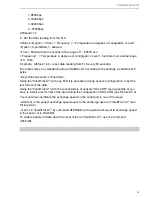
6) Next, you need to perform calibration procedures and calibration in accordance with Annex 1.
Connect and check.
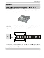
Once configuration is complete, the sensor can be attached to the device "M2M-Cyber GLX"
according to the following drawings:
ES2
RS232
черный
зеленый
желтый
красный
5
9
4
8
2
6
3
1
10
+12V
ES4
RS485
зеленый
желтый
черный
красный
5
9
4
8
2
6
3
1
10
+12V
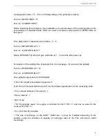
Check can be done by monitoring the debug information output to the terminal program used to
configure the device "M2M-Cyber GLX". If the connection is properly configured and the data
from the FLS will be prepared for shipment in the terminal window will be issued from time to
time information of the form:
9 Receive byte from user UART at 11:37:41 22/05/12
3E 8F 01 July 18 01 0F 00 4F
red
black
yellow
green
red
black
green
yellow


