background image

Magnetic Sonde

7 Installation and Maintenance

4423

32

Edition:003

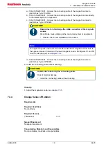
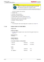
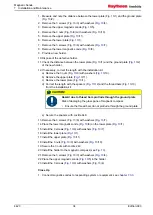
 CAUTION!

Hazard due to thread bars protrude through the ground plate

Risk of damaging the glass pane of magnetic compass
• Ensure the thread bars do not protrude through the ground plate.

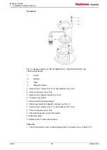
d) Secure the spacers with Loctite 648.

8. Install the plate.
9. Install the 3 nuts with washers.
10.Secure the 3 nuts with Loctite 243.
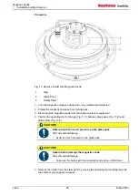
11.Install the holder to the magnetic compass, see 

Fig. 12

.

12.Remove the 3 screws (

Fig. 12

/3) with washers (

Fig. 12

/4).

13.Place the magnetic sonde in the new holder.
14.Install the 3 screws with washers.

Close Up

1. Connect magnetic sonde to responding system or equipment, see 

chapter 7.3.3

.

7.4.4.2 

Replace Holder for 108-010.NG003

Requirements

Required Conditions

1. The holder with the magnetic sonde is removed from the magnetic compass, see

chapter 7.4.2

.

Required Persons

1 Maintainer

1.0 h

Support Equipment

No support equipment

Consumables, Materials and Expendables

Loctite 648

06-0000 02

As required

Loctite 243

06-0000 03

As required

Spares

Holder

02-0000 03

1 EA

Kit, installation

03-0000 01

1 SE

Summary of Contents for 108-010.NG001 E01

Page 1: ...Magnetic Sonde Operator and Service Manual Type 108 010 NG001 E01 Type 108 010 NG002 E01 Type 108 010 NG003 E01 Type 108 010 NG004 E01 Edition 003 4423 ...

Page 2: ... gestattet Zuwiderhandlungen verpflichten zu Schadenersatz This document and its content are copyright protected Distribution reproduction and storage as well as translation and exploitation of this document and its content in whole or in parts and regardless of what form are prohibited without prior express written permission Offenders will be held liable for the payment of damages Änderungen die...

Page 3: ...tfit and Accessories 8 5 Operation 9 5 1 Safety Instructions for Operation 9 5 2 Setting Into Operation 9 5 2 1 Pre Operation Procedures 9 5 2 2 Pre Operation Procedures After Longer Time Setting Out of Operation 9 5 2 3 Setting Into Operation Procedures 9 5 3 Normal Operation Procedures 9 5 4 Setting Out of Operation 9 5 4 1 Setting Out of Operation Procedures 10 5 4 2 Post Operation Procedures 1...

Page 4: ...10 NG001 E01 27 7 4 3 2 Replace Magnetic Sonde 108 010 NG002 E01 27 7 4 3 3 Replace Magnetic Sonde 108 010 NG003 E01 28 7 4 3 4 Replace Magnetic Sonde 108 010 NG004 E01 29 7 4 4 Replace Holders of Magnetic Sonde 30 7 4 4 1 Replace Holder for 108 010 NG001 108 010 NG002 and 108 010 NG004 30 7 4 4 2 Replace Holder for 108 010 NG003 32 7 4 4 3 Replace Holder for 108 010 NG001 E01 108 010 NG002 E01 an...

Page 5: ...f Junction Box CP 500JB 17 Fig 8 Change Sense of Rotation 20 Fig 9 Adjust Magnetic Sonde 22 Fig 10 Measuring Points of Magnetic Sonde 24 Fig 11 Remove Holder with Magnetic Sonde 26 Fig 12 Replace Holder for 108 010 NG001 108 010 NG002 and 108 010 NG004 31 Fig 13 Replace Holder for 108 010 NG003 33 Fig 14 Replace Holder for 108 010 NG001 E01 108 010 NG002 E01 and 108 010 NG004 E01 36 Fig 15 Replace...

Page 6: ...Magnetic Sonde List of Figures 4423 IV Edition 003 ...

Page 7: ...Magnetic Sonde List of Tables Edition 003 V 4423 List of Tables Tab 1 Dimensional Drawings 5 Tab 2 Wiring Drawings 5 Tab 3 Special Tools Measurement and Test Equipment 13 Tab 4 Consumables 13 ...

Page 8: ...Magnetic Sonde List of Tables 4423 VI Edition 003 ...

Page 9: ...Magnetic Sonde List of Abbreviations Edition 003 VII 4423 List of Abbreviations EPA ESD Protected Area ESD Electrostatic Sensitive Device ISPC Illustrated Spare Parts Catalog ...

Page 10: ...Magnetic Sonde List of Abbreviations 4423 VIII Edition 003 ...

Page 11: ...ct us under the following address Raytheon Anschütz GmbH Tel 49 431 3019 0 Zeyestr 16 24 Fax 49 431 3019 291 D 24106 Kiel Email service raykiel com Germany www raytheon anschuetz com All rights reserved It is not allowed to copy any part of this manual neither mechanically electronically magnetically manually nor otherwise It is not allowed to store it in a database or distribute or forward it wit...

Page 12: ...ant but not hazard related 2 2 General Safety Instructions WARNING Danger due to nonadherence to general rules and regulations Risk of death or serious injury and material damage Observe all national and regional rules and regulations Observe all general rules and regulations that are specified for the work area Observe all instructions that are placed on the components or described in related doc...

Page 13: ...ive parts Keep the system closed Do not attempt to bypass or disable fuses 2 3 Electrostatic Sensitive Devices Fig 1 Electrostatic Sensitive Device Protected Area 1 Table Mat 2 Ground Cord 3 Dissipative Shoes 4 Floor Mat 5 Wrist Band 6 Wrist Strap 7 Common Ground 8 Ground Point Any product which is labeled as shown is electrostatic sensitive If proper Electrostatic Sensitive Device ESD precautions...

Page 14: ...ing the covers touching the connectors or handling the product components All ESD sensitive parts must be packed in metallized protective bags during shipping and handling outside any ESD Protected Area EPA ESD protected spare parts packages must not be opened closed out of an EPA All necessary equipment for these protective measures can be supplied on special order by Raytheon Anschütz ...

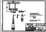
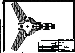
Page 15: ...3 3 List of Annex Drawings Tab 1 Dimensional Drawings Drawing No Designation 108 010 HP005 MAGNETIC SONDE Single 108 010 HP026 MAGNETIC SONDE Double 108 010 HP028 VORLAGE Centering mask Tab 2 Wiring Drawings Drawing No Designation 108 010 HP007 MAGNETIC SONDE ...

Page 16: ...e The magnetic sonde converts the visual display of the magnetic compass into an electrical signal 4 2 Hardware Breakdown of the System Equipment Fig 2 Hardware Breakdown of the System Equipment 1 108 010 NG001 E01 2 108 010 NG002 E01 3 108 010 NG003 E01 4 108 010 NG004 E01 ...

Page 17: ...ment Power Consumption n a Operation Temperature 25 C to 55 C 4 5 Technical Description The magnetic sonde consists of a halfround aluminum body with a screened connection cable It receives the power supply via the connection cable The magnetic sonde signal is transmitted via the connection cable Type 108 010 NG001 E01 Type 108 010 NG001 E01 has a connection cable with a 7 pole connector It has to...

Page 18: ...ion cable with a 5 pole metal connector It has to be connected to the related equipment via a junction box Type CP 500JB 4 6 Operating Elements and Indicators This system or equipment has no operating elements and indicators 4 7 Functional Description 4 7 1 Normal Operation The magnetic sonde scans the angular position of the magnetic field of the magnetic compass and converts it into a 3 phase co...

Page 19: ...only by skilled personnel 5 2 Setting Into Operation 5 2 1 Pre Operation Procedures Procedure 1 Switch on the power supply of the connected system or equipment 5 2 2 Pre Operation Procedures After Longer Time Setting Out of Operation This system or equipment requires no special pre operation procedures after longer time setting out of operation 5 2 3 Setting Into Operation Procedures The magnetic ...

Page 20: ...ormed via the connected system or equipment 5 4 2 Post Operation Procedures Procedure 1 Switch off the power supply of the connected system or equipment 5 4 3 Procedures for Longer Time Setting Out of Operation This system or equipment requires no special procedures for longer time setting out of operation 5 5 Emergency Operation Procedures This system or equipment has no emergency operation funct...

Page 21: ...red establish a proper electrical con nection Cable of the mag netic sonde is dam aged Replace the magnet ic sonde see chap ter 7 4 3 Magnetic sonde is defective Perform a function test of the magnet ic sonde see chap ter 7 4 1 1 The connected sys tem or equipment re ceives no data Junction box is de fective Replace the junc tion box see chap ter 7 4 5 Magnetic sonde is not adjusted Adjust the mag...

Page 22: ...the electric system only by skilled electricians CAUTION Hazard due to wrong disposal of harmful substances Risk of environmental damage that is caused by wrong disposal Adhere all national and regional disposal rules and regulations Adhere all disposal instructions that are placed on the components or described in related documentation 7 2 General Information 7 2 1 Reference to ISPC All maintenan...

Page 23: ...ls Measurement and Test Equipment Tab 3 Special Tools Measurement and Test Equipment Designation Reference to ISPC Quantity Tool operating 05 0000 02 1 Mask centering 05 0000 03 1 7 2 3 List of Consumables Tab 4 Consumables Designation Reference to ISPC Quantity Loctite 648 06 0000 02 As required Loctite 243 06 0000 03 As required Tie cable 06 0000 04 As required 7 3 Installation 7 3 1 Install Mag...

Page 24: ...jury and material damage Observe all general safety instructions Observe all safety instructions for maintenance CAUTION Hazard due to magnetic mounting material on the magnetic compass Risk of differing course display of the magnetic compass Use only nonmagnetic materials Procedure Fig 4 Install Magnetic Sonde 1 Glass Pane 2 Centering Mask 3 Adhesive Rings 4 Magnetic Sonde 1 Turn the magnetic com...

Page 25: ...e 7 Press for 15 s CAUTION Hazard due to premature strain of the adhesive bond Risk of material damage Do not strain the adhesive bond during the first 24 hours excessively 8 Fix the connecting cable for traction relief with a cable tie CAUTION Hazard due to buckling the connecting cable Risk of material damage Install the connecting cable without buckling Close Up 1 Connect the magnetic sonde to ...

Page 26: ...ety instructions Risk of death or serious injury and material damage Observe all general safety instructions Observe all safety instructions for maintenance Procedure Fig 5 Install Junction Box 1 Junction Box 2 Cover 3 Screw 1 Drill 2 holes M4 thread or 4 5 mm to the installation position in accordance to the drilling scheme ...

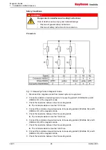
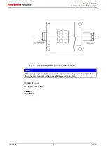
Page 27: ... Junction Box 2 Loosen the 4 screws Fig 6 3 3 Remove the cover Fig 6 2 4 Install the junction box Fig 5 1 with 2 suitable screws 5 Connect the cable of the responding system or equipment to the terminal strip see attached wiring diagram Fig 7 Terminal Assignments of Junction Box CP 500JB ...

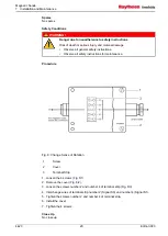
Page 28: ...ed see chapter 7 3 1 2 The junction box is installed see chapter 7 3 2 Required Persons 1 Maintainer 1 0 h Support Equipment No support equipment Consumables Materials and Expendables No consumables materials and expendables Spares No spares Safety Conditions WARNING Danger due to nonadherence to safety instructions Risk of death or serious injury and material damage Observe all general safety ins...

Page 29: ... cables Note The upper magnetic sonde is mirror inverted to the lower magnetic sonde Due to the opposed sense of rotation of the lower magnetic sonde the Signals S1 and S3 must be interchanged see chapter 7 3 4 d 108 010 NG004 E01 Connect the connecting cable of the magnetic sonde to junction box Type CP 500JB 2 Install the connecting cable without buckling CAUTION Hazard due to buckling the conne...

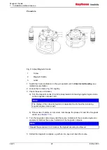
Page 30: ... Observe all safety instructions for maintenance Procedure Fig 8 Change Sense of Rotation 1 Screw 2 Cover 3 Terminal Strip 1 Loosen the 4 screws Fig 8 1 2 Remove the cover Fig 8 2 3 Loosen the screws number 2 and number 4 of terminal strip Fig 8 3 4 Interchange wires of terminal strip number 2 Signal S3 and number 4 Signal S1 5 Tighten the screws number 2 and number 4 of terminal strip 6 Install t...

Page 31: ...Support Equipment Label AHEAD 05 0000 04 1 EA Consumables Materials and Expendables Loctite 243 06 0000 03 As required Spares No spares Safety Conditions WARNING Danger due to nonadherence to safety instructions Risk of death or serious injury and material damage Observe all general safety instructions Observe all safety instructions for maintenance Note The adjustment of the magnetic sonde is onl...

Page 32: ...ng angular degree value on the magnetic compass card Note The display of the connected system or equipment must show the increasing angular degree value as well b If the sense of rotation is not correct interchange the phases S1 and S3 of magnetic sonde see chapter 7 3 4 4 Turn the magnetic sonde slowly until the course indication of the connected system or equipment matches the course indication ...

Page 33: ...em or equipment still matches the course indication of the magnetic compass 8 Secure the screws with Loctite 243 9 Install the label AHEAD Fig 9 3 to the magnetic sonde in the vessels ahead direction Note Adjust the double magnetic sonde like the single magnetic sonde Close Up No close up 7 4 Repair 7 4 1 Functional Test of Magnetic Sonde Requirements Required Conditions No conditions Required Per...

Page 34: ... the magnetic sonde 3 Check the resistance between the 2 measuring points The nominal resistance must be 151 Ohms 4 Connect the resistance measuring device to measuring points 4 SIGNAL S2 and 5 SIGNAL S1 of the magnetic sonde 5 Check the resistance between the 2 measuring points The nominal resistance must be 146 Ohms 6 Connect the resistance measuring device to measuring points 4 SIGNAL S2 and 3 ...

Page 35: ...emove Magnetic Sonde Requirements Required Persons 1 Maintainer 1 0 h Support Equipment Tool operating 05 0000 02 1 EA Consumables Materials and Expendables No consumables materials and expendables Spares No spares Safety Conditions WARNING Danger due to nonadherence to safety instructions Risk of death or serious injury and material damage Observe all general safety instructions Observe all safet...

Page 36: ...lated system or equipment 4 Position the operating tool to the gap Fig 11 1 between glass pane Fig 11 2 and holder plate Fig 11 3 CAUTION Hazard due to too much pressure on the glass pane Risk of material damage Avoid too much pressure to the glass pane CAUTION Hazard due to damage the magnetic sonde Risk of material damage Take care the holder with the magnetic sonde does not fall down 5 Remove t...

Page 37: ...consumables materials and expendables Spares Sonde magnetic 01 0000 02 1 EA Safety Conditions WARNING Danger due to nonadherence to safety instructions Risk of death or serious injury and material damage Observe all general safety instructions Observe all safety instructions for maintenance Procedure 1 Provide a new magnetic sonde 2 Remove the magnetic sonde see chapter 7 4 2 Close Up 1 Install th...

Page 38: ...serious injury and material damage Observe all general safety instructions Observe all safety instructions for maintenance Procedure 1 Provide a new magnetic sonde 2 Remove the magnetic sonde see chapter 7 4 2 Close Up 1 Install the magnetic sonde see chapter 7 3 1 7 4 3 3 Replace Magnetic Sonde 108 010 NG003 E01 Requirements Required Conditions No conditions Required Persons 1 Maintainer 0 1 h Su...

Page 39: ...see chapter 7 3 1 7 4 3 4 Replace Magnetic Sonde 108 010 NG004 E01 Requirements Required Conditions No conditions Required Persons 1 Maintainer 0 1 h Support Equipment No support equipment Consumables Materials and Expendables No consumables materials and expendables Spares Sonde magnetic 01 0000 05 1 EA Safety Conditions WARNING Danger due to nonadherence to safety instructions Risk of death or s...

Page 40: ...moved from the magnetic compass see chapter 7 4 2 Required Persons 1 Maintainer 1 0 h Support Equipment No support equipment Consumables Materials and Expendables Loctite 648 06 0000 02 As required Loctite 243 06 0000 03 As required Spares Holder 02 0000 02 1 EA Kit installation 03 0000 01 1 SE Safety Conditions WARNING Danger due to nonadherence to safety instructions Risk of death or serious inj...

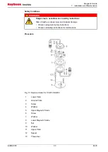
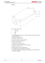
Page 41: ...nd the ground plate Fig 12 2 2 Remove the 3 screws Fig 12 3 with washers Fig 12 4 3 Remove the magnetic sonde Fig 12 5 4 Provide a new holder 5 Dispose of the defective holder 6 Check the distance between the plate Fig 12 1 and the ground plate of the new holder 7 If necessary correct the length with the installation kit a Remove the 3 nuts Fig 12 6 with washers Fig 12 7 b Remove the plate Fig 12 ...

Page 42: ...2 12 Remove the 3 screws Fig 12 3 with washers Fig 12 4 13 Place the magnetic sonde in the new holder 14 Install the 3 screws with washers Close Up 1 Connect magnetic sonde to responding system or equipment see chapter 7 3 3 7 4 4 2 Replace Holder for 108 010 NG003 Requirements Required Conditions 1 The holder with the magnetic sonde is removed from the magnetic compass see chapter 7 4 2 Required ...

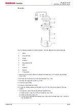
Page 43: ...of death or serious injury and material damage Observe all general safety instructions Observe all safety instructions for maintenance Procedure Fig 13 Replace Holder for 108 010 NG003 1 Lower Plate 2 Ground Plate 3 Screw 4 Washer 5 Upper Magnetic Sonde 6 Screw 7 Washer 8 Lower Magnetic Sonde 9 Nut 10 Washer 11 Upper Plate 12 Spacer 13 Thread bar ...

Page 44: ...wer plate Fig 13 1 d Correct the length with the spacers Fig 13 12 and the thread bars Fig 13 13 from the installation kit CAUTION Hazard due to thread bars protrude through the ground plate Risk of damaging the glass pane of magnetic compass Ensure the thread bars do not protrude through the ground plate e Secure the spacers with Loctite 648 13 Remove the 3 screws Fig 13 6 with washers Fig 13 7 1...

Page 45: ... the magnetic compass see chapter 7 4 2 Required Persons 1 Maintainer 1 0h Support Equipment No support equipment Consumables Materials and Expendables No consumables materials and expendables Spares Holder 02 0000 04 1 EA Safety Conditions WARNING Danger due to nonadherence to safety instructions Risk of death or serious injury and material damage Observe all general safety instructions Observe a...

Page 46: ...Fig 14 2 2 Remove the plate Fig 14 3 3 Remove the magnetic sonde Fig 14 4 4 Provide a new holder 5 Dispose of the defective holder 6 Install new holder to magnetic compass see Fig 14 7 Remove the 3 screws Fig 14 1 with washers Fig 14 2 8 Remove the plate Fig 14 3 9 Place the magnetic sonde in the holder 10 Install the plate 11 Replace the 3 screws with washers Close Up 1 Connect magnetic sonde to ...

Page 47: ...ass see chapter 7 4 2 Required Persons 1 Maintainer 1 0 h Support Equipment No support equipment Consumables Materials and Expendables Loctite 243 06 0000 03 As required Spares Holder 02 0000 05 1 EA Safety Conditions WARNING Danger due to nonadherence to safety instructions Risk of death or serious injury and material damage Observe all general safety instructions Observe all safety instructions ...

Page 48: ...ate 11 Lower Magnetic Sonde 1 Remove the 3 screws Fig 15 1 with washers Fig 15 2 2 Remove the upper plate Fig 15 3 3 Remove the upper magnetic sonde Fig 15 4 4 Remove the 3 nuts Fig 15 5 with washers Fig 15 6 5 Remove the plate Fig 15 7 6 Remove the 3 screws Fig 15 8 with washers Fig 15 9 7 Remove the lower plate Fig 15 10 8 Remove the lower magnetic sonde Fig 15 11 9 Provide a new holder 10 Dispo...

Page 49: ...cure the 3 nuts with Logtite 243 21 Install the new holder to the magnetic compass see Fig 15 22 Remove the 3 screws Fig 15 1 with washers Fig 15 2 23 Remove the upper plate Fig 15 3 24 Place the upper magnetic sonde Fig 15 4 in the holder 25 Install the upper plate Fig 15 3 26 Install the 3 screws Fig 15 1 with washers Fig 15 2 Close Up 1 Connect magnetic sonde to responding system or equipment s...

Page 50: ...ic mounting material on the magnetic compass Risk of differing course display of the magnetic compass Use only nonmagnetic materials Procedure Fig 16 Install Holder 1 Glass Pane 2 Centering Mask 3 Adhesive Rings 4 Holder 1 Turn the magnetic compass upside down see related documentation 2 Protect the magnetic compass from turning back 3 Clean and degrease the glass pane Fig 16 1 of the magnetic com...

Page 51: ...in the adhesive bond during the first 24 hours excessively Close Up No close up 7 4 5 Replace Junction Box Requirements Required Conditions 1 The junction box is defective Required Persons 1 Maintainer 1 0 h Support Equipment No support equipment Consumables Materials and Expendables No consumables materials and expendables Spares Box junction 04 0000 02 1 EA Safety Conditions WARNING Danger due t...

Page 52: ...emove the cover Fig 17 2 4 Remove the 2 screws fixing the junction box 5 Remove the junction box Fig 17 1 6 Provide a new junction box 7 Dispose of the defective junction box 8 Loosen the 4 screws Fig 17 3 of the new junction box 9 Remove the cover Fig 17 2 10 Install the junction box with 2 suitable screws 11 Connect the magnetic sonde to the new junction box 12 Connect the cable of the respondin...

Page 53: ...g 18 Terminal Assignments of Junction Box CP 500JB Note The terminal assignment of the vessel cable connection in the junction box depends on the connection diagrams of the responding system or equipment 13 Install the cover 14 Tighten the 4 screws Close Up No close up ...

Page 54: ... dry and dirt dust free Protect the equipment by corresponding packing material against damage Do not stack the components devices No special storage regulations are applicable Adhere the following environmental conditions Storage temperature 30 C to 70 C Humidity 80 relative humidity noncondensing Atmospheric pressure 600 hPa to 1 400 hPa 8 2 Transport During the transport of the components devic...

Page 55: ...12 02 10 ...

Page 56: ...07 10 11 Lut 23 11 11 ...

Page 57: ...07 10 11 Lut 23 11 11 ...

Page 58: ...12 01 10 ...

Page 59: ...Edition 001 Magnetic Sonde Illustrated Spare Parts Catalog 4423 108 010 NG001 E01 108 010 NG002 E01 108 010 NG003 E01 108 010 NG004 E01 ...

Page 60: ...tattet Zuwiderhandlungen verpflichten zu Schadenersatz Änderungen dieses Dokuments und dessen Inhalt bleiben vorbehalten This document and its content are copyright protected Distribution reproduction and storage as well as translation and exploitation of this document and its content in whole or in parts and regardless of what form are prohibited without prior express written permission Offenders...

Page 61: ...log Edition 001 3 4423 Illustrated Spare Parts Catalog Content 00 0000 Magnetic Sondes Variants 01 0000 Magnetic Sondes 02 0000 Holders 03 0000 Installation Kit 04 0000 Junction Boxes 05 0000 Special Tools and Test Equipment 06 0000 Consumables ...

Page 62: ...Magnetic Sonde Illustrated Spare Parts Catalog 4 4 Edition 001 Intentionally left blank ...

Page 63: ...4B Manufacturer This column comprises the name of the manufacturer If column 4A and 4b contain only one name then the supplier is also the manufacturer 5A Supplier Part No This column comprises the supplier part number of the spare part 5B Manufacturer Part No This column comprises the manufacturer part number of the spare part 6 UOI Unit of Issue The unit of issue determines the measure weight co...

Page 64: ...Magnetic Sonde Illustrated Spare Parts Catalog 4423 6 Edition 001 Magnetic Sondes Variants 00 0000 Sheet 1 of 1 ...

Page 65: ...hütz 00 0000 02 Magnetic Sondes Raytheon Anschütz see Fig Nr 01 0000 00 0000 03 Holders Raytheon Anschütz see Fig Nr 02 0000 00 0000 04 Installation Kit Raytheon Anschütz see Fig Nr 03 0000 00 0000 05 Junction Boxes Various Raytheon Anschütz see Fig Nr 04 0000 00 0000 06 Special Tools and Test Equipment Various Raytheon Anschütz see Fig Nr 05 0000 00 0000 07 Consumables Various Raytheon Anschütz s...

Page 66: ...Magnetic Sonde Illustrated Spare Parts Catalog 4423 8 Edition 001 Magnetic Sondes 01 0000 Sheet 1 of 1 ...

Page 67: ...Sondes Raytheon Anschütz 01 0000 02 Sonde Magnetic Raytheon Anschütz 4004077 EA 1 108 010 NG001 E01 Plastic Connector 01 0000 03 Sonde Magnetic Raytheon Anschütz 4004081 EA 1 108 010 NG002 E01 Ferrules 01 0000 04 Sonde Magnetic Raytheon Anschütz 4004070 EA 1 108 010 NG003 E01 Double Metal Connector 01 0000 05 Sonde Magnetic Raytheon Anschütz 4004084 EA 1 108 010 NG004 E01 Metal Connector ...

Page 68: ...Magnetic Sonde Illustrated Spare Parts Catalog 4423 10 Edition 001 Holders 02 0000 Sheet 1 of 1 ...

Page 69: ...2 0000 01 Holders Raytheon Anschütz 02 0000 02 Holder Raytheon Anschütz 3609674 EA 1 Single Version for NG001 NG002 NG004 02 0000 03 Holder Raytheon Anschütz 3610884 EA 1 Double Version for NG003 02 0000 04 Holder Raytheon Anschütz 3610885 EA 1 Single Version for NG001 E01 NG002 E01 NG004 E01 02 0000 05 Holder Raytheon Anschütz 3610886 EA 1 Double Version for NG003 E01 ...

Page 70: ...Magnetic Sonde Illustrated Spare Parts Catalog 4423 12 Edition 001 Installation Kit 03 0000 Sheet 1 of 1 ...

Page 71: ...schütz 3503223 EA 3 108 010 12 001 45 x 8 M4 03 0000 05 Standoff Raytheon Anschütz 3503281 EA 3 108 010 13 001 66 x 8 M4 03 0000 06 Ring adhesive Raytheon Anschütz 1500088 EA 2 108 010 00 003 Ø 60 mm 03 0000 07 Ring adhesive segments Raytheon Anschütz 3513803 EA 3 108 010 00 005 03 0000 08 Spacer Ettinger Raytheon Anschütz 05 74 058 1743351 EA 6 03 0000 09 Spacer Ettinger Raytheon Anschütz 05 74 1...

Page 72: ...Manufacturer Supplier Manufacturer Part No Supplier Part No UOI QI Remarks 03 0000 13 Nut hexagon Raytheon Anschütz ISO4032 M4 A4 70 1610305 EA 3 03 0000 14 Screw machine Raytheon Anschütz ISO4762 M3x6 A4 70 1601186 EA 3 03 0000 15 Screw machine Raytheon Anschütz ISO4762 M4x14 A4 70 1601237 EA 6 ...

Page 73: ...Magnetic Sonde Illustrated Spare Parts Catalog Edition 001 15 4423 Intentionally left blank ...

Page 74: ...Magnetic Sonde Illustrated Spare Parts Catalog 4423 16 Edition 001 Junction Boxes 04 0000 Sheet 1 of 1 ...

Page 75: ...Supplier Manufacturer Part No Supplier Part No UOI QI Remarks 04 0000 01 Junction Boxes Raytheon Anschütz 04 0000 02 Box junction Cassens Plath Raytheon Anschütz CB 500JB 2011376 EA 1 For NG004 NG003 E01 NG004 E01 04 0000 03 Box junction Raytheon Anschütz 134 089 EA 1 For NG001 NG001 E01 No longer available ...

Page 76: ...Magnetic Sonde Illustrated Spare Parts Catalog 4423 18 Edition 001 Special Tools and Test Equipment 05 0000 Sheet 1 of 1 ...

Page 77: ...ufacturer Part No Supplier Part No UOI QI Remarks 05 0000 01 Special Tool and Test Equipment Raytheon Anschütz 05 0000 02 Tool operating Wago Raytheon Anschütz 280 434 1722241 EA 1 05 0000 03 Mask centering Raytheon Anschütz 5024230 EA 1 108 010 HP028 05 0000 04 Label AHEAD Raytheon Anschütz 3500486 EA 1 135 079 90 002 ...

Page 78: ...Magnetic Sonde Illustrated Spare Parts Catalog 4423 20 Edition 001 Consumables 06 0000 Sheet 1 of 1 ...

Page 79: ...Supplier Part No UOI QI Remarks 06 0000 01 Consumables Raytheon Anschütz 06 0000 02 Loctite 648 Henkel Raytheon Anschütz Typ 0648 1970008 EA 1 Not illustrated 06 0000 03 Loctite 243 Henkel Raytheon Anschütz Typ 0243 1970007 EA 1 Not illustrated 06 0000 04 Tie cable Hellerman TYTON Raytheon Anschütz 818 00032 1170082 EA 1 Not illustrated ...

Page 80: ...Magnetic Sonde Illustrated Spare Parts Catalog 4423 22 Edition 001 Intentionally left blank ...

Reviews: