Magnetic Sonde
7 Installation and Maintenance
4423
34
Edition:003
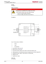
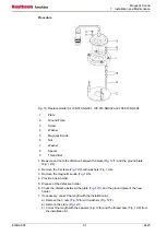
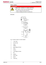
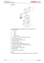
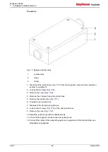
1. Measure and note the distance between the lower plate (
(
/2).
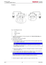
2. Remove the 3 screws (
3. Remove the upper magnetic sonde (
4. Remove the 3 nuts (
/9) with washers (
5. Remove the upper plate (
/1).
7. Remove the 3 screws (
8. Remove the lower magnetic sonde (
/8).
9. Provide a new holder.
10.Dispose of the defective holder.
11.Check the distance between the lower plate (
of the new holder.
12.If necessary, correct the length with the installation kit.
a) Remove the 3 nuts (
c) Remove the lower plate (
/1).
d) Correct the length with the spacers (
/12) and the thread bars (
/13)
from the installation kit.
CAUTION!
Hazard due to thread bars protrude through the ground plate
Risk of damaging the glass pane of magnetic compass
• Ensure the thread bars do not protrude through the ground plate
e) Secure the spacers with Loctite 648.
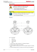
13.Remove the 3 screws (
14.Place the lower magnetic sonde (
/7).
16.Install the lower plate (
/1).
18.Install the 3 nuts (
19.Secure the 3 nuts with Loctite 243.
20.Install the holder to the magnetic compass (see
21.Remove the 3 screws (
22.Place the upper magnetic sonde (
/4).
Close Up
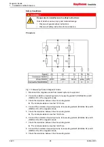
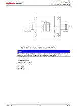
1. Connect magnetic sondes to responding system or equipment, see
.
Summary of Contents for 108-010.NG001 E01
Page 6: ...Magnetic Sonde List of Figures 4423 IV Edition 003 ...
Page 8: ...Magnetic Sonde List of Tables 4423 VI Edition 003 ...
Page 10: ...Magnetic Sonde List of Abbreviations 4423 VIII Edition 003 ...
Page 55: ...12 02 10 ...
Page 56: ...07 10 11 Lut 23 11 11 ...
Page 57: ...07 10 11 Lut 23 11 11 ...
Page 58: ...12 01 10 ...
Page 62: ...Magnetic Sonde Illustrated Spare Parts Catalog 4 4 Edition 001 Intentionally left blank ...
Page 73: ...Magnetic Sonde Illustrated Spare Parts Catalog Edition 001 15 4423 Intentionally left blank ...
Page 80: ...Magnetic Sonde Illustrated Spare Parts Catalog 4423 22 Edition 001 Intentionally left blank ...

