Magnetic Sonde
7 Installation and Maintenance
4423
22
Edition:003
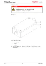
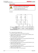
Procedure
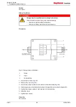
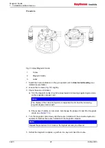
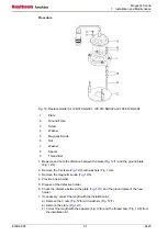
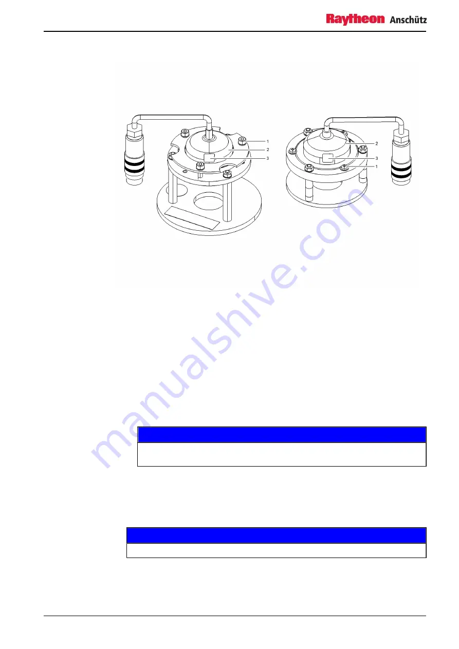
Fig. 9: Adjust Magnetic Sonde
1
Screw
2
Magnetic Sonde
3
Label
1. Switch the course indication on the gyro operator unit to
Uncorrected Heading
, see
related documentation.
3. Check the sense of rotation.
a) Turn the magnetic sonde (
/2) slowly towards increasing angular degree value
on the magnetic compass card.
Note
The display of the connected system or equipment must show the increasing
angular degree value as well.
b) If the sense of rotation is not correct, interchange the phases S1 and S3 of magnetic
4. Turn the magnetic sonde slowly until the course indication of the connected system or
equipment matches the course indication of the magnetic compass.
Note
Repeat the procedure 3 to 4 times so the highest accuracy is achieved.
5. Deflect the magnetic compass, e.g with an iron key and check the course.
Summary of Contents for 108-010.NG001 E01
Page 6: ...Magnetic Sonde List of Figures 4423 IV Edition 003 ...
Page 8: ...Magnetic Sonde List of Tables 4423 VI Edition 003 ...
Page 10: ...Magnetic Sonde List of Abbreviations 4423 VIII Edition 003 ...
Page 55: ...12 02 10 ...
Page 56: ...07 10 11 Lut 23 11 11 ...
Page 57: ...07 10 11 Lut 23 11 11 ...
Page 58: ...12 01 10 ...
Page 62: ...Magnetic Sonde Illustrated Spare Parts Catalog 4 4 Edition 001 Intentionally left blank ...
Page 73: ...Magnetic Sonde Illustrated Spare Parts Catalog Edition 001 15 4423 Intentionally left blank ...
Page 80: ...Magnetic Sonde Illustrated Spare Parts Catalog 4423 22 Edition 001 Intentionally left blank ...


