background image

25

0423-M001-2

J17

RISERVATO AL PERSONALE AUTORIZZATO ALL'INSTALLAZIONE - ONLY FOR INSTALLATION-AUTHORIZED STAFF

IST DEM ZUR INSTALLATION AUTORISIERTEN PERSONAL VORBEHALTEN - SEULEMENT POUR LE PERSONNEL AUTORISE A L'INSTALLATION - RESERVADO

 AL PERSONAL ENCARGADO DE LA INSTALACION

b) (

Solo per sollevatori 4 colonne

)

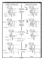
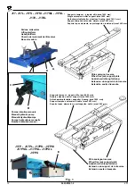
Consultando gli schemi di 

Fig. 11

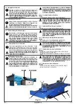
, regolare la posizione

verticale della staffa di trattenimento 

1

 tramite le apposite

asole e bloccarla con le viti.

NOTA: In particolare, per i ponti senza sollevatore inte-
grato aventi pedane per assetto , rispettare Y (19 mm).

c) Ripetere la procedura anche sul lato opposto.
d) Rif. 

Fig. 11

. Fare scorrere la traversa per tutta la lunghezza

della pedana verificandone il corretto movimento. La staffa
di trattenimento 

1

 non deve interferire con il bordo della

pedana.
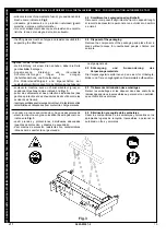
Rif. 

Fig. 12

. Durante lo scorrimento della traversa sulla

pedana, effettuare in più punti la verifica della quota 

X

.

Per effettuare questa verifica occorre allontanare dalle
pedane entrambi gli sfili 

2

 delle traverse, facendo in modo

che le staffe di trattenimento 

vadano in appoggio ai bordi

interni delle pedane (

vedi zona A

).

Se la quota 

dovesse risultare maggiore di quella indicata,

riportare gli sfili in posizione di lavoro ed aggiungere un'ul-
teriore distanziale. Effettuare nuovamente la procedura di
controllo della quota 

X

.

b) (

For 4-post lifts only

)

Referring to diagrams in 

Fig. 11

, adjust holder bracket 

1

vertical position through the special slots, and then tighten
screws.

NOTE: In particular, for lifts without lift table and with
platforms for wheel track alignment, respect Y (19 mm).

c) Repeat the procedure also on the opposite side.
d) Ref. 

Fig. 11

. Slide wheel-free jack along the whole platform,

making sure it moves properly. Holder bracket 

1

 does not

have to interfere with platform edge.
Ref. 

Fig. 12

. While wheel-free jack is sliding onto platform,

check 

X

 value in different positions.

To carry out this check, move both wheel-free jacks sliding
members 

2

 away from platforms, with holder brackets 

1

resting onto platforms inner edges (

see area A

).

If value 

X

 is higher than the specified one, move sliding

members in working position, and add one more spacer.
Then, re-check 

X

 value.

b) (

Nur für 4-Säulen-Hebebühnen

)

Unter Bezugnahme auf die Schemas der 

Abb. 11

 die

senkrechte Position des Haltebügels 

1

 über die

entsprechenden Langlöcher regulieren, dann die
Schrauben festziehen.

HINWEIS: Insbesondere bei den Hebebühnen ohne
integrierten Radfreiheber das Maß Y (19 mm) einhalten,
da sie Fahrschienen für die Achsvermessung enthalten.

c) Das Verfahren auch an der gegenüberliegenden Seite

wiederholen.

d) Bezug auf 

Abb. 11

. Den Achsheber über die gesamte Länge

der Plattform entlang schieben und dabei die korrekte
Bewegung überprüfen. Den Haltebügel 

1

 darf nicht mit dem

Rand der Plattform in Interferenz kommen.
Bezug auf 

Abb. 12

. Während der Achsheber an der Plattform

entlang gleitet, das Maß 

an mehreren Stellen überprüfen.

Um diese Überprüfung durchführen zu können, müssen
beide Auszugsteile 

2

 des Achshebers von den Plattformen

distanziert werden, so dass die Haltebügel 

1

 an den intern

liegenden Rändern der Plattform zum Aufliegen kommen
(

siehe Bereich A

).

Sollte das Maß 

über dem angegebenen Maß liegen, die

Auszugsteile in ihre Arbeitsposition bringen und ein weiteres
Distanzstück anfügen. Das Kontrollverfahren des Maßes 

X

wiederholen.

b) (

Uniquement pour les élévateurs 4 colonnes

)

En consultant les schémas 

Fig. 11

, régler la position verti-

cale de la bride de retenue 

1

 au moyen des fentes prévues

et la bloquer à l’aide des vis.

REMARQUE : En particulier, pour les ponts sans élévateur
intégré ayant des plates-formes pour la géométrie,
respecter Y (19 mm).

c) Répéter la procédure du côté opposé.
d) Réf. 

Fig. 11

. Faire coulisser la traverse de levage sur toute

la longueur de la plate-forme en en contrôlant le mouvement.
La bride de retenue 

1

 ne doit pas interférer avec le bord de

la plate-forme.

Réf. 

Fig. 12

. Durant le coulissement de la traverse de levage

sur la plate-forme; effectuer la vérification de la cote 

en

plusieurs points.
Pour effectuer cette vérification, il est nécessaire d’éloigner
des plates-formes les rallonges 

2

 des poutres de levage; de

façon que les brides de retenue 

soient en appui sur les

bords internes des plates-formes (

voir zone A

).

Si la cote 

est supérieure à celle indiquée, reporter les

rallonges en position de fonctionnement et ajouter une
autre cale. Effectuer à nouveau la procédure de contrôle de
la cote 

X

.

b) (

Sólo para elevadores 4 columnas

)

Consultando los esquemas en la 

Fig. 11

, ajustar la posición

vertical del soporte de retención 

1

, mediante los ojales

específicos y sujetarlo con los tornillos.

NOTA: En particular, para los puentes sin elevador
integrado con plataformas de alineación, respetar Y (19
mm).

c) Repetir el procedimiento también en el lado opuesto.
d) Ref. 

Fig. 11

. Desplazar el gato de elevación a lo largo de toda

la plataforma, comprobando que el movimiento sea correcto.
El soporte de retención 

1

 no debe tocar el borde de la

plataforma.
Ref. 

Fig. 12

. Durante el deslizamiento del gato de elevación

sobre la plataforma, controlar el valor

 X

 en varios puntos.

Para efectuar esta prueba es necesario alejar de las
plataformas ambas extensiones 

2

 de los gatos de elevación,

de tal manera que los soportes de retención 

1

 entren en

contacto con los bordes internos de las plataformas 

(véase

zona A).

Si el valor 

X

 resultara mayor del indicado, volver a colocar

las extensiones en posición de trabajo y añadir un separador
suplementario. Llevar a cabo de nuevo el procedimiento de
control del valor 

X

.

Summary of Contents for J17

Page 1: ...o 3 40037 Pontecchio Marconi Bologna Italy Phone 39 051 6781511 Telex 510697 RAV I Fax 39 051 846349 e mail aftersales ravaglioli com Im Zweifelsfall oder bei R ckfragen wenden Sie sich bitte an den n...

Page 2: ...0423 M001 2 SIMBOLOGIA UTILIZZATA NEL MANUALE SYMBOLS USED IN THE MANUAL IN DER BETRIEBSANLEITUNG VERWENDETE ZEICHEN SYMBOLES UTILISES DANS LA NOTICE SIMBOLOG A UTILIZADA EN EL MANUAL X X _ q _ X X X...

Page 3: ...chtbzw das Lesen des Handbuchs erm glicht werden Jeder Schaden der sich aus einem Nichtbeachten der in diesem Handbuch angef hrtenAngabenableitenl t k nnendemHerstellernichtangelastetwerdenundbefreien...

Page 4: ...pour la zone d installation 16 3 3 Connexion pneumatique Versions P 17 3 4 Installation sur pont avec chemin de roulement de type A B C 21 3 5 Installation sur pont avec chemin de roulement de type D...

Page 5: ...ATION 32 7 ENTRETIEN 32 7 1 R tablissement du niveau de l huile 33 7 2 Vidange de l huile pompe hydraulique 34 7 3 Vidange de l huile pompe pneumohydraulique 34 7 4 Nettoyage du clapet et du filtre 35...

Page 6: ...n lesdangersautantquepossible Onamis en lumi re les risques r siduels possibles dans cette notice tout comme sur la machine par le biais de pictogrammes autocollants Fig 0 1 En cas d endommagement de...

Page 7: ...7 0423 M001 2 J17 J17 J17P J17L J17PL X...

Page 8: ...8 J17 0423 M001 2 J17S J17PS J17SI J17PSI X...

Page 9: ...9 0423 M001 2 J17 J17SIL J17PSIL J17SL J17PSL X...

Page 10: ...10 J17 0423 M001 2 J17X X J17PX...

Page 11: ...11 0423 M001 2 J17 J17PXL X J17XL...

Page 12: ...tampons extension double max 1600 mm Soporte topes elemento de prolongaci n doble max 1600 mm Fig 1 C B Pompa idraulica manuale Manual hydraulic pump ManuelleHydraulikpumpe Pompe hydraulique manuelle...

Page 13: ...C maximum pressure valve D mechanicalstop E rise pedal for pneumatic hydraulic model 1 DESCRIPCION Y USO APROPIADO 1 1 Descripci n de la m quina Travesa o de funcionamiento hidr ulico con parada mec n...

Page 14: ...para deslizamiento colocaci n travesa o sobre el puente acoplamiento mec nico que evita la bajada accidental de la carga 2 3 1 Fig 2 X X X accessori che possono essere utilizzati sui prodotti trattati...

Page 15: ...iderstandsf higkeit und Eigenschaften der Lastaufnahmemittel m ssen f r das St tzen der gehobenen the lifting means must be of a type and resistance suitable for supporting the lifted load sollevare l...

Page 16: ...the machine properly check with the spare parts table 3 2 Checking the minimum requirements for the place of installation Check that the area in which the machine is to be installed has the following...

Page 17: ...best to use filtered and lubricated air Make connections using a connector as shown in Fig 4 3 3 Pneumatischer Anschluss Ausf hrung P Der Luftversorgungsdruck f r die Ausf hrung P darf die 10 bar nic...

Page 18: ...ATION AUTORISIERTEN PERSONAL VORBEHALTEN SEULEMENT POUR LE PERSONNEL AUTORISE A L INSTALLATION RESERVADO AL PERSONAL ENCARGADO DE LA INSTALACION 4 columns lifts 4 columns lifts Scissors lifts 4 column...

Page 19: ...DEM ZUR INSTALLATION AUTORISIERTEN PERSONAL VORBEHALTEN SEULEMENT POUR LE PERSONNEL AUTORISE A L INSTALLATION RESERVADO AL PERSONAL ENCARGADO DE LA INSTALACION Fig 5 Pedana Tipo A A type platform Peda...

Page 20: ...UTORIZZATO ALL INSTALLAZIONE ONLY FOR INSTALLATION AUTHORIZED STAFF IST DEM ZUR INSTALLATION AUTORISIERTEN PERSONAL VORBEHALTEN SEULEMENT POUR LE PERSONNEL AUTORISE A L INSTALLATION RESERVADO AL PERSO...

Page 21: ...er the crosspiece to a distance of about 5 cm from the footboard position the brackets of the crosspiece Fig 6 lower the crosspiece onto the edge and check that it slides easily 3 5 Instructionsforins...

Page 22: ...der Halteb gel 1 und die korrekte Montage in Abh ngigkeit zur Hebeb hne dargestellt an der der Achsheber montiert wird Hebeb hnen Serie 600 6350 Den Halteb gel 1 Abb 9 anordnen 4 S ulen Hebeb hnen4oh...

Page 23: ...di ponte sollevatore vedi Fig 10 e 11 interporre n 1 oppure n 3 spessori A e le relative viti B di opportuna lunghezza 16mm oppure 18mm Le viti non devono sporgere dalla staffa della traversa al fine...

Page 24: ...edana H 70 mm 600 Series lifts with platform edge H 70 mm Sollevatori Serie 600 Sollevatori Serie 6350 con bordo pedana H 38 mm 600 Series lifts 6350 Series lifts with platform edge H 38 mm Sollevator...

Page 25: ...e L nge der Plattform entlang schieben und dabei die korrekte Bewegung berpr fen Den Halteb gel 1 darf nicht mit dem Rand der Plattform in Interferenz kommen BezugaufAbb 12 W hrendderAchsheberanderPla...

Page 26: ...ung der Einrichtung Nach der Installation wird das befugte Personal das diese Arbeiten vorgenommen hat eine oder mehrere Inbetriebsetzungen und komplette Funktionszyklen durchf hren Dabei sollte man m...

Page 27: ...ealer 4 MODE D EMPLOI 4 1 Pr cautions pour l emploi et formation du personnel pr pos l utilisation L utilisation de la machine n est consentie qu au personnel autoris ayant suivi une formation ad quat...

Page 28: ...lets or such like must not be worn long hair must be tied back shoes must be suitable for the work to be done Accident prevention regulations provided for by current laws should always be respected Th...

Page 29: ...EGNO TRAVERSA E AI SUPPORTI TAMPONE 4 2 1 Comandi traversa idraulica Salita posizionare la traversa sotto i punti di appoggio 4 2 Description of controls Always fit the mechanical safety pin Fig 13 wh...

Page 30: ...hydraulic system so the wheel free jack drops pull back the support arms 1 and 2 4 2 2 Pneumatic hydraulic wheel free jack controls Up position the jack under the supporting points pull out arms 1 an...

Page 31: ...la pulizia e la regolazione dove possibile Ogni manomissione o modifica dell apparecchiatura nonpreventivamenteautorizzatedalcostruttoresolle vano quest ultimo da danni derivanti o riferibili agli att...

Page 32: ...propres Les parties mobiles doivent tre propres et lubrifi es Si la traverse n a pas t utilis e pendant une longue p riode de temps il est recommand de contr ler les joints pour s assurer qu ils ne s...

Page 33: ...mba hidr ulica 2 Fig 14 de mando del travesa o y si es necesario reponerlo de la siguiente manera bajar completamente el travesa o quitar la tapa 3 el nivel del aceite debe coincidir con el borde 1 3...

Page 34: ...tappo 3 lt 1 5 7 2 Changing the oil hydraulic pump The oil must be completely changed every 200 operating hours as follows fully lower the wheel free jack position the jack horizontally with cap 3 tur...

Page 35: ...ing the valve and filter Cleaning should be done using petrol and compressed air Pay special attention when fitting and removing the valve and filter Regularly clean the air filter replacing if necess...

Page 36: ...bbero risultare danneggiate in seguito al deposito di polvere Provvedere ad ingrassare le parti che si potrebbero danneggiare in caso di essiccazione In occasione della rimessa in funzione sostituire...

Page 37: ...ni in condizioni di massima sicurezza Il costruttore non pu essere ritenuto responsabile per danni provocati a persone animali o cose in caso di interventi da parte di persone non autorizzato e profes...

Page 38: ...rating and or adjusting in condition of maximum safety The manufacturer will not accept any responsibility for damage to people animals and objects caused by manoeuvres by unauthorised and unqualified...

Page 39: ...rung der Eingriffe und oder Einstellungen unter Ber cksichtigung der erforderlichen Sicherheitsbedingungen erteilt werden k nnen Der Hersteller kann f r eventuelle durch Eingriffe die von unbefugtem P...

Page 40: ...les r glages en toute s curit La responsabilit du fabricant ne peut tre mise en cause pour des dommages provoqu s des personnes des animaux ou des choses dus l intervention de personnes non autoris e...

Page 41: ...o los ajustes necesarios en toda seguridad El fabricante declina cualquier responsabilidad por da os a personas animales o cosas debidos a la intervenci n de personal no autorizado ni cualificado prof...

Page 42: ...LAZIONE ONLY FOR INSTALLATION AUTHORIZED STAFF IST DEM ZUR INSTALLATION AUTORISIERTEN PERSONAL VORBEHALTEN SEULEMENT POUR LE PERSONNEL AUTORISE A L INSTALLATION RESERVADO AL PERSONAL ENCARGADO DE LA I...

Page 43: ...NE ONLY FOR INSTALLATION AUTHORIZED STAFF IST DEM ZUR INSTALLATION AUTORISIERTEN PERSONAL VORBEHALTEN SEULEMENT POUR LE PERSONNEL AUTORISE A L INSTALLATION RESERVADO AL PERSONAL ENCARGADO DE LA INSTAL...

Page 44: ...permette una rapida individuazione dei principali gruppi che costituiscono le macchine e delle relative tavole per l ordinazione delle parti di ricambio 11 2 Spare parts summary Fig 15 shows the mach...

Page 45: ...E 5 PNEUMO HYDRAULIC PUMP TAFEL 1 STRUKTUR HEBER TAFEL 2 HALTER UND AUSSTATTUNG TAFEL 3 HYDRAULIKANLAGE TAFEL 4 HYDRAULIKPUMPE TAFEL 5 LUFTHYDRAULISCHE PUMPE PLANCHE1 STRUCTURE TRAVERSE PLANCHE 2 BRID...

Page 46: ...lida per i modelli Apply to models N tavola Table no Indice di modifica Change index J17 0423 M001 2 46 STRUTTURA TRAVERSA WHEEL FREE JACK STRUCTURE J17 J17L J17P J17PL J17PS J17PSI J17PSIL J17PSL J17...

Page 47: ...y to models N tavola Table no Indice di modifica Change index J17 0423 M001 2 47 2 6 J17 J17L J17P J17PL J17PS J17PSI J17PSIL J17PSL J17PX J17PXL J17S J17SI J17SIL J17SL J17X J17XL STAFFE E DOTAZIONE...

Page 48: ...Valida per i modelli Apply to models N tavola Table no Indice di modifica Change index J17 0423 M001 2 48 3 0 J17 J17L J17P J17PL J17PS J17PSI J17PSIL J17PSL J17PX J17PXL J17S J17SI J17SIL J17SL J17X...

Page 49: ...azione tavola Table definition Valida per i modelli Apply to models N tavola Table no Indice di modifica Change index J17 0423 M001 2 49 4 0 POMPA IDRAULICA HYDRAULIC PUMP J17 J17L J17S J17SI J17SIL J...

Page 50: ...la Table definition Valida per i modelli Apply to models N tavola Table no Indice di modifica Change index J17 0423 M001 2 50 POMPA PNEUMO IDRAULICA PNEUMO HYDRAULIC PUMP 5 0 J17P J17PL J17PS J17PSI J...

Page 51: ...sions please have routine inspections performed by specialized personnel WICHTIG Wir bitten Sie zu ber cksichtigen dass regelm ige Kontrollbesuche seitens des Installateurs besonders wichtig sind und...

Page 52: ...t du pont l vateur V rifier le niveau de l huile dans la pompe V rifier l alimentation pneumatique appropri e si n cessaire 10 bars max air lubrifi Les bras compl tement extraits v rifier le levage d...

Page 53: ...richtige Druckluftzufuhr wo notwendig berpr fen max 10 bar geschmierte Luft Das Heben mit den ganz um eine Achse eines Wagens von 2000 kg ausgezogenen Armen berpr fen DATUM UNTERSCHRIFT DES MONTEURS...

Page 54: ...richtige Druckluftzufuhr wo notwendig berpr fen max 10 bar geschmierte Luft Das Heben mit den ganz um eine Achse eines Wagens von 2000 kg ausgezogenen Armen berpr fen DATUM UNTERSCHRIFT DES MONTEURS...

Page 55: ...richtige Druckluftzufuhr wo notwendig berpr fen max 10 bar geschmierte Luft Das Heben mit den ganz um eine Achse eines Wagens von 2000 kg ausgezogenen Armen berpr fen DATUM UNTERSCHRIFT DES MONTEURS...

Page 56: ...IONALE DATA FIRMA DELL INSTALLATORE RANDOM INSPECTIONS DATE INSTALLER SIGNATURE GELEGENTLICHEKONTROLLE DATUM UNTERSCHRIFT DES MONTEURS CONTROL OCCASIONNEL DATE SIGNATURE DE L INSTALLATEUR CONTROL OCAS...

Page 57: ...N Fig 16 Portata Capacity Tragf higkeit Capacit Capacidad Numero di matricola Serial number Seriennummer Num ro de s rie N mero de matr cula Anno di costruzione Year of manufacture Baujahr Ann e de fa...

Page 58: ...58 J17 0423 M001 2...
Reviews: