30 P
ARAGON
II
/
C
OMMAND
C
ENTER
I
NTEGRATION
S
OLUTIONS
D
EPLOYMENT
G
UIDE
G1 Models
1
2
3
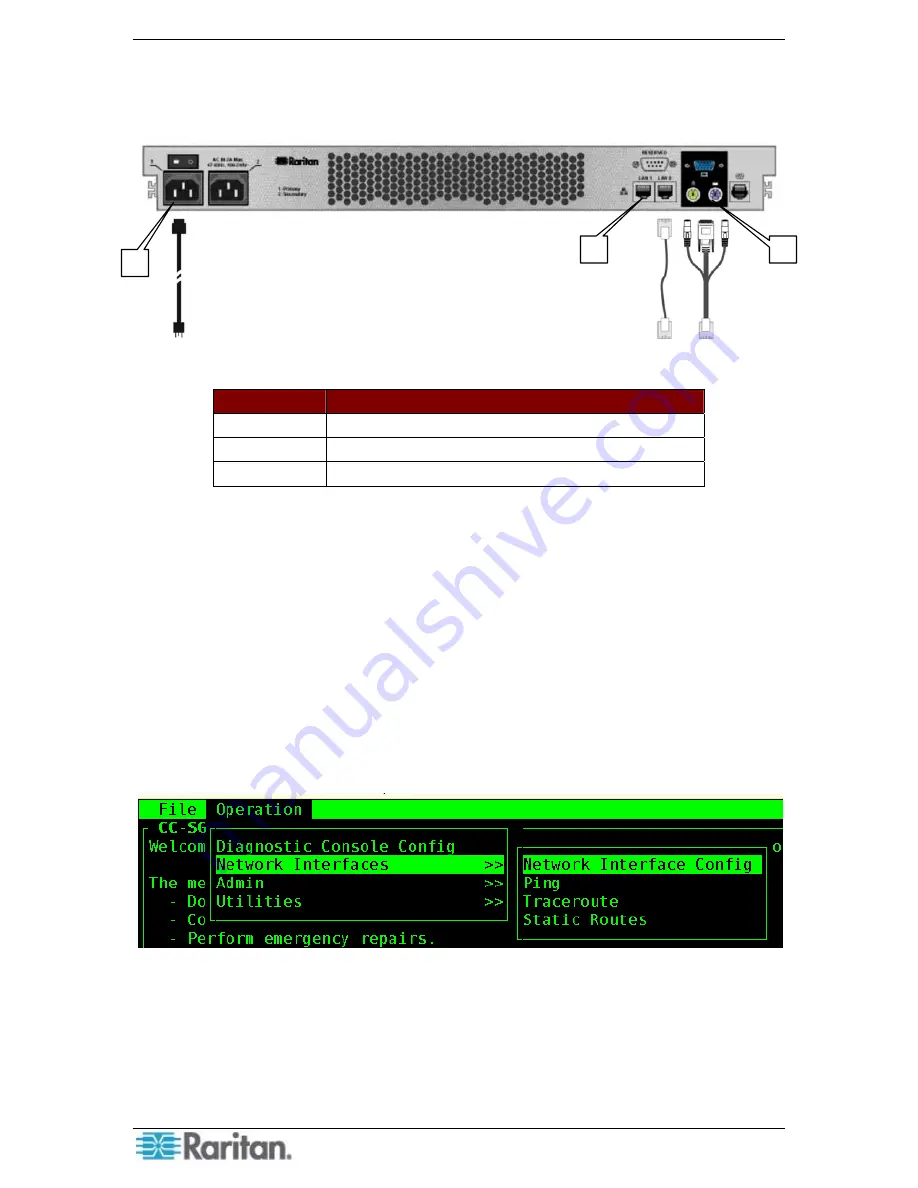
Figure 25 G1 CommandCenter Secure Gateway Back-panel
N
UMBER
C
OMPONENT
1 Ethernet
ports
2 Power
ports
3
Keyboard, video, and mouse ports
1.
Connect the network LAN cable to the primary Ethernet port on the rear panel of the
CommandCenter Secure Gateway unit. Connect the other end of the cable to the network.
2.
Attach the included AC power cord to the Primary port on the rear panel of the
CommandCenter Secure Gateway unit. Plug the other end or the cord into an AC power
outlet.
3.
Power ON CommandCenter Secure Gateway.
4.
Connect your keyboard, video, and mouse cables to the corresponding ports on the rear panel
of the CommandCenter Secure Gateway unit. When prompted, login with the username
admin
and password
raritan
to access the
Diagnostic Console
.
5.
If this is the first time the CC-SG has been accessed, you will be prompted to change your
password. Type the old password, then a new password, followed by the new password again
to confirm the change.
6.
After logging in, type
Ctrl-X
.
Figure 26 CommandCenter Secure Gateway Diagnostic Console Interface
7.
Select the
Operation
menu, then
Network Interfaces
, then
Network Interface Config
to
configure the network settings for CC-SG.
8.
Select a
DHCP
or
Static
IP address configuration. If Static is selected, type the IP address of
CC-SG and select
Save.
9.
When you are finished, CommandCenter Secure Gateway will restart.
Summary of Contents for Paragon II
Page 4: ......
Page 8: ......
Page 12: ...4 PARAGON II COMMANDCENTER INTEGRATION SOLUTIONS DEPLOYMENT GUIDE...
Page 22: ......
Page 32: ......
Page 36: ...28 PARAGON II COMMANDCENTER INTEGRATION SOLUTIONS DEPLOYMENT GUIDE...
Page 40: ......
Page 50: ...42 PARAGON II COMMANDCENTER INTEGRATION SOLUTIONS DEPLOYMENT GUIDE...
Page 53: ...APPENDIX A P2SC COMPATIBILITY LIST 45...
Page 60: ......
Page 63: ......


