CGTH I
NSTALLATION
, O
PERATION
AND
S
ERVICE
M
ANUAL
40 of 55
SECTION 11: GAS SERVICE INSTALLATION
11.1 Install Gas Supply Lines
A 3/8" gas s
u
pply connection is req
u
ired as sho
w
n
. To check system press
u
re, a
pl
u
gged 1/8" NPT tapping is req
u
ired
u
pstream of the
man
u
al gas sh
u
t-off
v
al
v
e s
u
pplied
w
ith the heater.
Before connecting the heater to the s
u
pply system,
v
erify that all high press
u
re
testing of the gas piping has
b
een completed. Do not
high press
u
re test (greater than 1/2" psi/3.5 kPa) the
gas piping
w
ith the
bu
rner connected. The appliance
m
u
st
b
e isolated from the gas piping system
b
y clos-
ing man
u
al gas sh
u
t-off
v
al
v
e d
u
ring any press
u
re
testing at press
u
res less than or eq
u
al to 1/2" psi (3.5
kPa).
Follo
w
these instr
u
ctions to ens
u
re a safe gas s
u
pply
system installation:
1. S
u
pport all gas piping
w
ith s
u
ita
b
le pipe hanging
materials.
2. Use
w
ro
u
ght iron or
w
ro
u
ght steel pipe and mal-
lea
b
le iron fittings. The
u
se of copper t
ub
e and
b
rass fittings is accepta
b
le
w
hen s
u
ch
u
se is in
compliance
w
ith local codes. All pipe, t
ub
e and
fittings sho
u
ld
b
e ne
w
and free from defects.
Caref
u
lly ream the pipe and t
ub
e ends to
remo
v
e o
b
str
u
ctions and
bu
rrs.
3. Use LP gas resistant joint compo
u
nd on all
threads.
4. Check the pipe and t
ub
e connections for leaks
b
efore placing heating eq
u
ipment into ser
v
ice.
When checking for gas leaks,
u
se a soap and
w
ater sol
u
tion;
never use an open flame
.
FIGURE 36: Gas Supply Lines
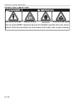
WARNING
Explosion Hazard
Tighten gas hose fittings to connect gas
supply according to Figure 36.
Leak test all components of gas piping
before operation.
Gas can leak if piping is not installed
properly.
Do not high pressure test gas piping with
heater connected.
Failure to follow these instructions can result
in death, injury or property damage.
Heater
Pipe Union
Manual Gas Shut-off Valve
3/8" NPT Pipe Nipple
Not Supplied
by Rapid Engineering
NOTE:
A pl
u
gged 1/8" NPT tapping m
u
st
b
e pro
v
ided
u
pstream of the gas
s
u
pply to the heater.
Summary of Contents for CGTH-30
Page 2: ......
Page 4: ......
Page 6: ......
Page 52: ...CGTH INSTALLATION OPERATION AND SERVICE MANUAL 46 of 55 FIGURE 38 Manometer Reading ...
Page 60: ...CGTH INSTALLATION OPERATION AND SERVICE MANUAL 54 of 55 ...
Page 62: ......
Page 63: ......
Page 64: ......


