SECTION 9: V
ENTING
I
NSTALLATION
31 of 55
FIGURE 22: Elbow Assembly End View
7. Interlock the loops at each end of the spring
coils together as sho
w
The loops
w
ill lock together to prod
u
ce a contin-
u
o
u
s coil spring spacer aro
u
nd the o
u
tside diam-
eter of the 3" (8 cm) el
b
o
w
.
8. Fit the 5" (13 cm) el
b
o
w
o
v
er the 3" (8 cm) el
b
o
w
).
FIGURE 23: Elbow Assembly Cross Section View
9. Attach 3" (8 cm) el
b
o
w
portion of 90° el
b
o
w
kit to
the 3" (8 cm) fl
u
e pipe (length 'A').
Use hi
g
h
temperature silicone sealant and 3 sheet-
metal screws.
(
)
FIGURE 24: Elbow Assembly
10.Completely assem
b
le the 3" (8 cm)
v
ent lengths
A, B and el
b
o
w
and attach to the heater. P
u
t the
v
ent collar on the 3" (8 cm)
v
ent. All joints m
u
st
b
e sealed
w
ith high temperat
u
re sealant and
sheet metal scre
w
s. (
FIGURE 25: Elbow Assembly for Vent Collar
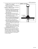
11. Attach the
v
ent collar to the heater. Hold the 5"
(13 cm)
v
ent material
u
p to the 3" (8 cm)
v
ent
and mark the req
u
ired length. Note the length
m
u
st
b
e s
u
fficient for a minim
u
m of 1 1/2" (4 cm)
o
v
erlap at
b
oth ends. C
u
t the
v
ent to length from
the non crimped end. Wrap the 3" (8 cm) t
ub
e
w
ith the 5" (13 cm)
v
ent and snap the
v
ent
together. Attach the 5" (13 cm)
v
ent at
b
oth
ends. All joints m
u
st
b
e sealed
w
ith high temper-
at
u
re sealant and sheet metal scre
w
s. (
)
FIGURE 26: Vent Collar and 5" Vent Attachment
3" (8 cm)
Elbow
1" (2.5 cm)
Diameter Spring
Interlock Loops
as shown
5" (13 cm)
Diameter Elbow
3" (8 cm)
Diameter Elbow
1" (2.5 cm)
Diameter Spring
6" (15 cm)
2.75" (6 cm)
Hi
g
h
T
e
m
pera
tu
re
Sili
co
ne
3
x Sel
f
Drill S
c
rew
s
Sprin
g
5" (13 cm)
Elbow
Spring
Heater
5" (13 cm)
Vent Collar
Stainless
Steel Tab
on
Turbulator
3x Self Drill Screws and
High Temperature Silicone
3" (
8
cm)
5" (13 cm)
3x Sheetmetal Screws and
High Temperature Silicone
1 1/2"
(4 cm)
Min.
1 1/2"
(4 cm)
Min.
1 1/2" (4 cm) Min.
1 1/2"
(4 cm)
Min.
Summary of Contents for CGTH-30
Page 2: ......
Page 4: ......
Page 6: ......
Page 52: ...CGTH INSTALLATION OPERATION AND SERVICE MANUAL 46 of 55 FIGURE 38 Manometer Reading ...
Page 60: ...CGTH INSTALLATION OPERATION AND SERVICE MANUAL 54 of 55 ...
Page 62: ......
Page 63: ......
Page 64: ......


