SECTION 9: V
ENTING
I
NSTALLATION
29 of 55
face of the
bu
rner
w
ith high temperat
u
re silicone
sealant and sec
u
re the connection
w
ith three
sheetmetal scre
w
s.
8. From the exterior of the
bu
ilding, slip the
v
ent
terminal onto the 3" (8 cm) fl
u
e pipe and g
u
ide
the slee
v
e portion of the
v
ent terminal o
v
er the
5" (13 cm) air s
u
pply pipe that is fl
u
sh
w
ith exte-
rior s
u
rface of
w
all. Sec
u
re air
v
ent pipe to the
v
ent terminal collar
w
ith silicone sealant.
9. Sec
u
re the
v
ent terminal to the exterior s
u
rface
of the
w
all.
NOTE:
If the protr
u
ding 3" (8 cm) fl
u
e pipe is directly
b
elo
w
and
w
ithin 24" (60 cm) of the
bu
ilding
soffit, the optional
v
ent extension sho
u
ld
b
e
u
sed to pre
v
ent fl
u
e gasses from degrading
bu
ilding s
u
rfaces.
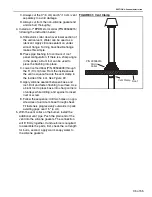
FIGURE 19: Horizontal Installation Side View
9.3.1 Bird Screen Installation
The
b
ird screen s
u
pplied
w
ith the heater m
u
st al
w
ays
b
e installed
w
ith the gal
v
anized
v
ent option. The
screen is to
b
e installed directly in the end of the 3" (8
cm) fl
u
e pipe or in the
v
ent terminal extension a
v
ail-
a
b
le as an option. Both screen installations are
descri
b
ed
b
elo
w
.
Installing
b
ird screen in 3" (8 cm) fl
u
e pipe:
1. Insert the
b
ird screen into the inside diameter of
the 3" (8 cm) fl
u
e pipe as sho
w
2. Sec
u
re the
b
ird screen in position
w
ith a sheet-
metal scre
w
.
Installing
b
ird screen in optional
v
ent terminal
extension:
1. Insert the
b
ird screen into the inside diameter of
the
v
ent terminal extension as sho
w
n
.
2. Using the handle from a hammer, or other simi-
lar de
v
ice, p
u
sh the
b
ird screen into the
v
ent
extension as far as possi
b
le.
3. Orient the
v
ent extension as sho
w
. Slip the extension onto 3" (8 cm) fl
u
e
pipe as far as possi
b
le; sec
u
re the
v
ent exten-
sion to the fl
u
e pipe
w
ith three sheetmetal
scre
w
s.
FIGURE 20: Bird Screen Installation
10' (3 m) max.
2' 6" (76.2 cm) min.
Optional Vent
Extension
3" (7.6 cm)
Flue Pipe
5" (12.5 cm) Air
Supply Pipe
Side View
Heater
Slope down 1/4"
(.6 cm) per foot
towards vent
terminal
Vent
Terminal
3" (7.6 cm) pipe is
slid through
end of terminal
6" (15.2 cm)
min.
Bird
Screen
O
p
t
i
o
nal
V
en
t
Ex
t
en
s
i
o
n
B
ir
d
S
c
reen
5
"
(
1
3 cm
)
V
en
t
Pipe
3"
(8
cm
)
Fl
u
e
Pipe
Summary of Contents for CGTH-30
Page 2: ......
Page 4: ......
Page 6: ......
Page 52: ...CGTH INSTALLATION OPERATION AND SERVICE MANUAL 46 of 55 FIGURE 38 Manometer Reading ...
Page 60: ...CGTH INSTALLATION OPERATION AND SERVICE MANUAL 54 of 55 ...
Page 62: ......
Page 63: ......
Page 64: ......


