


19. Manually turn the cross feed hand wheel
counterclockwise and move the cutting tools outward
toward the edge of the rotor to remove any rust build-up or
high areas on the outer edge.
20. After cleaning up the outer edge of the rotor manually
feed the cutting tools inward towards the center of the rotor
to a point slightly beyond the contact surface of the brake
pads being careful not to run the carbide inserts into the
hub portion of the rotor.
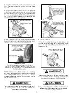
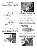
21.Turn both tool bit controls (OUTER KNURLED
KNOBS) to the desired depth-of cut then lock them in
position by tightening the dial lock knobs.
USE THESE GENERAL GUIDELINES
TO DETERMINE THE DEPTH-OF-CUT
Either rough or finish cuts may be taken to resurface a
rotor. Generally, finish cuts should be 0.004” (0.10 mm)
to 0.006” (0.15 mm) per side. Very shallow cuts of less
than 0.004” (10 mm) per side tend to reduce tool bit life
because the heat generated during reconditioning isn’t
transferred to the rotor efficiently. Rough cuts may be
taken from 0.006” to 0.010” per side.
IMPORTANT NOTE
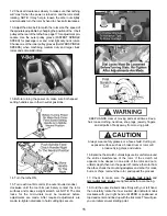
Hold OUTER knobs with one hand and turn CLOCK-
WISE to move cutting tips inward towards rotor. There
are 10 large graduations on each dial indicator. Each mark
represents 0.002” english ( 0.05 mm metric ).
22. Engage the automatic cross feed to begin the cut by
moving the lever to the desired speed. The cross feed will
stop automatically when the cutting tools have moved all
the way across the face of the rotor.
IMPORTANT NOTE
For roughing cuts, move the cross feed lever to the
FAST position. Rough cuts may be taken from 0.006” to
0.010” per side.
23. Manually feed the cutting tools inward towards the
center of the rotor to a point slightly beyond the contact
surface of the brake pads being careful not to run the
carbide inserts into the hub portion of the rotor.
24. Turn the end knob of each tool bar micro-dial
individually to set each tool bit to the desired depth-of cut.
Remove only enough material to clean up each side.
25. Engage the automatic cross feed to begin another cut.
26. When the tool bits have cleared the rotor, disengage
the cross feed and turn the lathe OFF.
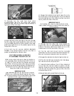
27. Inspect the brake surfaces. If part of the surface was
not cut, leave the tool bars locked in position, turn the
lathe ON, slowly turn the cross feed handwheel clockwise
until the outer tool reaches the groove at the rotor hub,
and repeat steps 20 -23.
28. Repeat steps until a smooth finish cut is made.
16


