Ranger Products RL4500 Installation And Operation Manual Download Page 12

IMPORTANT NOTE

If the hand wheel does not turn freely, check to make

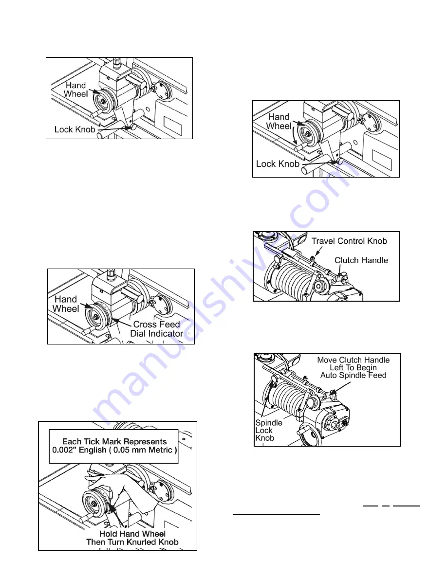
sure the cross feed lock knob is loosened.

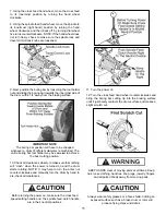
13. Examine the scratch cut making sure it is uniform
around the entire circumference of the drum. If the scratch
cut appears to be deeper on one side of the drum and not
a  uniform depth, then turn the power off, remove the drum
from the arbor, check the mounting adapters and arbor for
nicks, burrs, or chips, then remount the drum, and repeat
steps 4 - 13 until a uniform scratch cut is achieved.

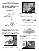
14. Holding the cross feed hand wheel firmly in position with
your left hand, carefully rotate the cross feed dial indicator
(the outer, knurled knob) with your right hand until ZERO is
positioned at top dead center and lined up with the tick mark.
This will give you an initial zero-set starting point.

15. Turn the spindle feed hand wheel clockwise until the
boring bar reaches the innermost part of the drum. Be
careful not to crash the boring bar and cutting tip on the
inside wall of the drum or damage to tooling may result.

16. There are 100 graduations on the dial indicator. Each
tick mark represents 0.002” ( 0.05 mm metric ).

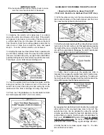
GUIDELINES TO DETERMINE THE DEPTH-OF-CUT 

• Rough cuts should be no deeper than 0.020”.

• Finish cuts should be no shallower than 0.004” deep.

17. With the lathe running, turn the cross feed hand wheel
dial counterclockwise to the depth desired and then lock
the cross feed by tightening the lock knob.

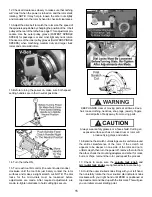
18. Set the automatic feed shut-off by sliding the travel control
lock knob on the limit rod to a point that approximately equals
the depth of the drum and tighten the knob in place. The limit
rod will then automatically disengage the clutch handle and
stop the spindle feed when it reaches this point.

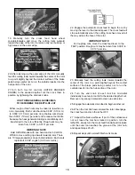
19. Double check to make sure the spindle lock knob is
loosened then engage the spindle feed clutch handle (move
to the left) to begin auto-feed drum resurfacing. To make sure
the clutch gear is fully engaged, hold the clutch handle to the
left until the spindle feed handwheel starts turning.

By engaging the spindle feed clutch handle, the spindle and
arbor will move the mounted brake drum to the left. The
spindle feed rate can be adjusted by using the spindle
variable speed dial. Adjust the feed rate depending on the
surface finish you desire. Fast for rough cuts and slower for
finish cuts. 

REMEMBER! 

Spindle feed must be adjusted

with the lathe running only. Do not try to adjust speed dial
without the drive motor running or gear damage will occur. 

20. After the first cut is made, repeat  steps 14 - 19 until a
smooth finish cut is made. 

12

Summary of Contents for RL4500

Page 1: ...ed in shipment must be made by the purchaser against the transportation company at the time shipment is received BE SAFE Your new Ranger brake lathe was designed and built with safety in mind However your overall safety can be increased by proper training and thoughtful operation on the part of the operator DO NOT operate or repair this equipment without reading this manual and the important safet...

Page 2: ... cautions in this manual For additional copies or further information contact Bend Pak Inc Ranger Products 1645 Lemonwood Dr Santa Paula CA 93060 1 805 933 9970 www bendpak com OPERATOR PROTECTIVE EQUIPMENT Personal protective equipment helps make brake service safer However equipment does not take the place of safe operating practices Always wear durable work clothing during service activity Shop...

Page 3: ... of the owner is to read and follow these instructions Follow all installation instructions Make sure installation conforms to all applicable Local State and Federal Codes Rules and Regulations such as State and Federal OSHA Regulations and Electrical Codes Carefully check the unit for correct initial function Read and follow the safety instructions Keep them readily available for machine operator...

Page 4: ... Never use compressed air to blow and clear chips Chips and dust may be driven between machined parts and into bearings causing undue wear They may also contact persons in the area causing personal injury BEFORE YOU BEGIN Receiving The shipment should be thoroughly inspected as soon as it is received The signed bill of lading is acknowledgement by the carrier of receipt in good condition of shipme...

Page 5: ...nging accessories USE FACTORY APPROVED TOOLS ONLY Don t force a tool or an attachment to do a job for which it was not designed The use of improper accessories may cause risk of injury to operator or bystanders Use only as described in this manual Use only manufacturer s recommended attachments KEEP WORK AREA CLEAN and well lighted Cluttered areas and benches invite accidents LOCATE POWER CORD SAF...

Page 6: ...delivery system supplies a constant flow of oil to the bearings High impact storage case for tools and accessories STANDARD EQUIPMENT INCLUDES Combination Brake Lathe With Standard Bench Micrometer Type Twin Tool Holder Head Boring Bar Carbide Cutting Tools 6 Sided Carbide Cutting Inserts 1 Arbor Spring Arbor Nut Spare Bulb For Lamp Inside Floating Adapters Self Aligning Spacer Outside Floating Ad...

Page 7: ...7 ...

Page 8: ...he correct amount and type of oil Add oil as necessary to reach the correct mark on the dipstick Use only EP 80 90 gear oil Oil level should be checked often BRAKE ROTOR DRUM INSPECTION 1 Before attempting any resurfacing rotor and or drum inspection is necessary Determine the manufacturer s specifications from an approved specification guide 2 Using a digital micrometer or other measuring tool re...

Page 9: ... Spindle speed is adjustable by changing the position of the V belt pulley on the rear of the lathe See page 17 Cross Feed The cross feed forward and aft draws the tool bit micro dial twin cutters or boring bar across the face of a brake rotor or flywheel when the cross feed speed setting handle is engaged The cross feed may also be operated manually without engaging the feed handle using the cros...

Page 10: ... size hubless adapter The centering cone will fit into the center hole of the drum from the inside to center the drum on the arbor Fill out the remaining shaft with various adapters and or spacers as needed IMPORTANT NOTE The arbor nut has REVERSE THREADS Tighten by turning the arbor nut COUNTER CLOCKWISE IMPORTANT NOTE The self aligning spacer should always be used next to the arbor nut when tigh...

Page 11: ...lder may be swiveled to achieve the best cutting position 10 Check all clearances closely to make sure that nothing will crash when the power is turned on and the drum starts rotating NOTE It may help to turn the arbor nut counter clockwise and manually turn the drum by hand to pre check all clearances Before turning the power on make sure the cross feed speed setting handle and the spindle feed c...

Page 12: ...should be no deeper than 0 020 Finish cuts should be no shallower than 0 004 deep 17 With the lathe running turn the cross feed hand wheel dial counterclockwise to the depth desired and then lock the cross feed by tightening the lock knob 18 Set the automatic feed shut off by sliding the travel control lock knob on the limit rod to a point that approximately equals the depth of the drum and tighte...

Page 13: ...le minimum limits discard it NOTE This check requires a measurement in only one spot if both braking surfaces cleaned up 100 because the turning operation assures almost absolute parallelism Preparing For Twin Cutters 1 Remove the boring bar and tool holder brackets 2 Using the spindle feed hand wheel move the spindle to its innermost right hand position by turning the hand wheel clockwise and the...

Page 14: ...ety shield if it was removed for storage then review the cautions and dangers section and the general safety information at the beginning of this manual The safety shield is easily screwed onto the twin cutter in the threaded mounting hole provided IMPORTANT NOTE Do not overtighten arbor nut when mounting rotors on the spindle The pressure of one hand on the wrench is sufficient to tighten If cent...

Page 15: ...the micro dials must be loosened before adjustments are made After required adjustments are made re tighten dial locks to hold cutting tips secure KEEP HANDS clear of moving parts at all times Keep hair loose clothing neckties shop rags jewelry fingers and all parts of body away from moving parts Always wear safety glasses or a face shield Cutting an exposed surface such as a brake drum or rotor w...

Page 16: ... inward towards rotor There are 10 large graduations on each dial indicator Each mark represents 0 002 english 0 05 mm metric 22 Engage the automatic cross feed to begin the cut by moving the lever to the desired speed The cross feed will stop automatically when the cutting tools have moved all the way across the face of the rotor IMPORTANT NOTE For roughing cuts move the cross feed lever to the F...

Page 17: ...d surface finish depends on the correct relationship of the spindle speed with the cross feed speed As a general rule slower spindle speeds require slower cross feed speeds Also deeper cuts normally dictate that a slower cross feed rate and or spindle speed may be necessary Multi Speed Settings The RL4500 brake lathe has three different pulley selections 1 The small outside pulley at the motor in ...

Page 18: ...s and covers are in place Replace any damaged or missing safety decal s They are available from the factory On a daily basis inspect the unit and check to be certain that all systems are operating normally Follow detailed inspection and testing procedures for various components at regular intervals GENERAL LUBRICATION Oil the ways of the head assembly and thread screw periodically with a light oil...

Page 19: ...19 ...

Page 20: ...20 ...

Page 21: ...21 ...

Page 22: ...22 ...

Page 23: ...23 ...

Page 24: ...24 ...

Page 25: ...25 ...

Page 26: ... misuse shipping damage improper installation or lack of required maintenance This warranty is exclusive and in lieu of all other warranties expressed or implied In no event shall Ranger Products be liable for special consequential or incidental damages for the breach or delay in performance of the warranty Ranger Products reserves the right to make design changes or add improvements to its produc...

Page 27: ...27 ...

Page 28: ...For Parts Or Service Contact Bend Pak Inc Ranger Products 1645 Lemonwood Dr Santa Paula CA 93060 Tel 1 805 933 9970 Fax 1 805 933 9160 www bendpak com www rangerproducts com ...

Reviews: