


12. Check all clearances closely to make sure that nothing
will “crash” when the power is turned on and the rotor starts
rotating. NOTE: It may help to loosen the arbor nut slightly
and manually turn the rotor by hand to check all clearances.
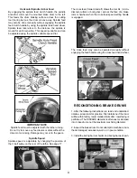
13. Adjust the drive belt to match the rotor size.The speed of
the spindle is adjustable by changing the position of the V-belt
pulley at the rear of the lathe. See page 17 for adjustment pro-
cedure. Use the outer pulley groove (FASTEST SPINDLE
SPEED) for passenger car and most light duty truck rotors.
Choose one of the inner pulley grooves (SLOWER SPINDLE
SPEEDS) when machining medium duty and larger truck
rotors and some solid rotors.
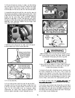
13. Before turning the power on, make sure both speed
setting handles are in their neutral positions.
14. Turn the lathe ON.
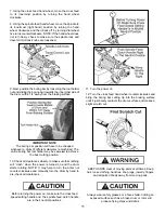
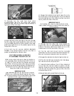
15. Turn each tool bit control (the outer knurled knobs)
clockwise until the tool bits just barely contact the rotor
surfaces and makes a slight scratch cut. NOTE: The dial
locks for the micro-dials must be loosened before
adjustments are made. After required adjustments are
made, re-tighten dial locks to hold cutting tips secure.
KEEP HANDS clear of moving parts at all times. Keep
hair, loose clothing, neckties, shop rags, jewelry, fingers,
and all parts of body away from moving parts.
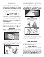
Always wear safety glasses or a face shield. Cutting an
exposed surface such as a brake drum or rotor will
produce flying chips and debris.
16. Examine the scratch cut making sure it is uniform around
the entire circumference of the rotor. If the scratch cut
appears to be deeper on one side of the rotor and not a
uniform depth, then turn the power off, remove the rotor from
the arbor, check the mounting adapters and arbor for nicks,
burrs, or chips, remount the rotor, and repeat the process.
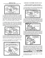
17. Check to make sure the
spindle lock knob
and
micro-dial lock knobs
are tightened before continuing.
18. Hold the outer knurled knobs firmly with your left hand,
then carefully rotate the inner knurled dial indicator knobs
clockwise with your right hand until ZERO is positioned at
top dead center and lined up with the tick mark. This will give
you an initial zero-set starting point.
15


